


DA98D User Manual
51
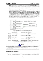
(2) Switch on control circuit power (temporarily not switching on the main circuit power) and
the point on the display of the drive unit will shine. If alarm occurs, examine the wiring.
(3) Set the control mode (parameter No.4) as speed operation mode (set as 2) and set PA43
parameter as 0. Set parameter No.24
~
27 according to needs.
(4) Switch on the main circuit power.
(5) Render servo on (SON) ON after confirming that there is no alarm or any other abnormal
condition, then the motor will be activated and under the operation state of internal speed
1.
(6) Change the states of input signal SC1 and SC2 to make the motor rotate at the given
speed.
7.3 Adjustment
z
Wrong parameter setting may cause equipment failure or accidents. Confirm validity
of parameter setting before starting the system.
z
It is recommended to no-load commissioning should be conducted before
commissioning with load.
1
)
Adjustment in Basic Gains
(1) Speed Control
①
The value speed proportion gain (parameter No.5) should be set as large as possible
under the precondition that no vibration will be caused. Generally, the greater the load
inertia is, the larger the value of speed proportion gain shall be set.
②
The value of speed integral time constant (parameter No.6) shall be set as low as possible
according to the given conditions. If the value of speed integral time constant is set too low,
the response speed will be improved but it is also easy to cause vibration. So under the
precondition that no vibration will be caused, the value shall be set as low as possible. For
if the value is too high, the speed will have a great change when the load is changed.
(2) Position Control
①
Set proper speed proportion gain and speed integral time constant according to the
above-motioned methods.
②
Set position feed-forward gain (parameter NO.10) as 0%.
③
Within the range of stability, the value of position proportion gain (parameter No.9) shall be
set as large as possible. If the value of position proportion gain is set too high, the position
command will be easily traced and have small lag error, but it is prone to cause vibration
when it stops positioning.
④
If an extremely high performance in position tracing is required, the value of position
feed-forward gain can be increased. But if the value is set too high, it may cause
over-adjustment.
Note: When the value of position proportion gain is relatively low, the system will be
stable, but the position tracing performance will be impaired and the lag error
increased.
2
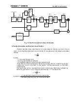
)
Chart for Adjustment in Basic Parameters
Attention
Summary of Contents for DA98D
Page 1: ...DA98D Digital AC Servo Drive Unit User Manual V5 00 ...
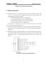
Page 15: ...DA98D User Manual 4 Fig 1 1 Appearance of Servo Drive unit 2 Servo motor appearance ...
Page 16: ...DA98D User Manual 5 Fig 1 2 Servo Motor Appearance ...
Page 23: ...DA98D User Manual 12 Fig 3 1 Standard Wiring for Position Control Mode AM26LS32 Receiver ...
Page 24: ...DA98D User Manual 13 Fig 3 2 Standard Wiring for Speed Control Mode AM26LS32 Receiver ...
Page 71: ...DA98D User Manual 60 Installation Dimension Drawing for BS 120 Model ...
Page 72: ...DA98D User Manual 61 Installment Dimension Drawing for BS 200 Model ...
Page 73: ...DA98D User Manual 62 Installment Dimension Drawing for BS 300 Model ...
Page 74: ...DA98D User Manual 63 Installment Dimension Drawing for BD 80 Model ...
Page 75: ...DA98D User Manual 64 Installment Dimension Drawing for BD 120 Model ...