


DA98D User Manual
43
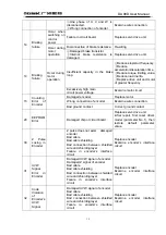
“cn- oFF” : The main circuit is not discharged and the servo system does
not work;
“cn- CH” : The main circuit is charged but the servo system does not work
( the servo is not on or alarm occurs);
“cn- on” : The main circuit is charged and the servo system is under
operation,
Note 2
:
Linear velocity only displays 4 digits.
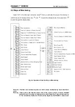
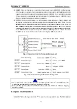
6.3 Parameter Setting
z
Only after No.0 parameter is set as the corresponding value can other parameters be
changed.
z
Except No.1 parameter, the parameter will take effect immediately after it is set. Wrong
parameter setting may cause wrong operation of the equipment, which will result in
accidents.
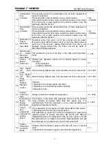
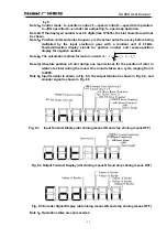
Select “PA-” in the first layer, then press down
to enter the parameter setting mode. Use
and
to select serial number of the parameter and enter
to display the value, which can be
changed by using
and
. Click
or
for one time, the parameter value will be increased
or decreased by 1; press down
or
and hold on, the parameter value will be increased or
decreased continuously. When the parameter is changed, the decimal point on LED nixie tube at the
furthest right side will shine, then press down
to confirm the validity of the parameter changed
and the decimal point will stop shining. The changed parameter value will be immediately reflected
in the control operation. Use
or
to go on with parameter changing, after which click down
to return to the parameter selecting mode. If you are not satisfied with the changed parameter
value, do not press down
for confirmation but use
to cancel the parameter changing
operation, restore the original value and return to the parameter selecting mode.
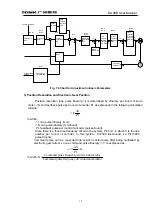
Fig. 6.6 Operation Chart for Parameter Setting
Attention
Summary of Contents for DA98D
Page 1: ...DA98D Digital AC Servo Drive Unit User Manual V5 00 ...
Page 15: ...DA98D User Manual 4 Fig 1 1 Appearance of Servo Drive unit 2 Servo motor appearance ...
Page 16: ...DA98D User Manual 5 Fig 1 2 Servo Motor Appearance ...
Page 23: ...DA98D User Manual 12 Fig 3 1 Standard Wiring for Position Control Mode AM26LS32 Receiver ...
Page 24: ...DA98D User Manual 13 Fig 3 2 Standard Wiring for Speed Control Mode AM26LS32 Receiver ...
Page 71: ...DA98D User Manual 60 Installation Dimension Drawing for BS 120 Model ...
Page 72: ...DA98D User Manual 61 Installment Dimension Drawing for BS 200 Model ...
Page 73: ...DA98D User Manual 62 Installment Dimension Drawing for BS 300 Model ...
Page 74: ...DA98D User Manual 63 Installment Dimension Drawing for BD 80 Model ...
Page 75: ...DA98D User Manual 64 Installment Dimension Drawing for BD 120 Model ...


