


DA98D User Manual
66
remainder, which means that position errors exist. The maximal error is the minimal
rotation value (minimal resolution) of the motor.
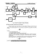
9.3 Stop Features
Under position control mode, there will be a difference between the command pulse and
feedback pulse when using pulse train to control the servo motor. This difference will be
accumulated in the position error meter and form the following relationships with the
command pulse frequency, electronic gear ratio and position proportion gain:
ε
=
p
K
G
f
×
*
in which,
ε
:
Lag Pulse (Puls);
f: Command Pulse Frequency (Hz);
Kp: Position Proportion Gain (1/S);
G: Electronic Gear Ratio.
Note: the above relationship is reached under the condition that position
feed-forward gain is 0%. If the position feed-forward gain is >0%, the lag pulse
will be less than that in the above calculation formula.
9.4 Calculation Method for Selecting Models of Servo System and Position
Controller
1)
Command displacement and actual displacement
:
in which,
S: actual displacement mm;
I: command displacement mm;
δ
: minimal unit of CNC mm;
CR: command frequency
multiplication coefficient;
CD: command frequency division coefficient
DR: servo frequency multiplication coefficient;
DD: servo frequency division coefficient;
ST: grade division value per round of motor;
ZD: gear number of side gear of motor;
ZM: gear number of side gear of lead screw;
L: pitch of lead screw mm
Generally, S=I, which means command value equals actual value.
2) Maximal Command Speed of CNC:
L
ZM
ZD
ST
DD
DR
CD
CR
I
S
⋅
⋅
⋅
⋅
⋅
=
1
δ
max
60
f
CD
CR
F
≤
⋅
×
δ
Summary of Contents for DA98D
Page 1: ...DA98D Digital AC Servo Drive Unit User Manual V5 00 ...
Page 15: ...DA98D User Manual 4 Fig 1 1 Appearance of Servo Drive unit 2 Servo motor appearance ...
Page 16: ...DA98D User Manual 5 Fig 1 2 Servo Motor Appearance ...
Page 23: ...DA98D User Manual 12 Fig 3 1 Standard Wiring for Position Control Mode AM26LS32 Receiver ...
Page 24: ...DA98D User Manual 13 Fig 3 2 Standard Wiring for Speed Control Mode AM26LS32 Receiver ...
Page 71: ...DA98D User Manual 60 Installation Dimension Drawing for BS 120 Model ...
Page 72: ...DA98D User Manual 61 Installment Dimension Drawing for BS 200 Model ...
Page 73: ...DA98D User Manual 62 Installment Dimension Drawing for BS 300 Model ...
Page 74: ...DA98D User Manual 63 Installment Dimension Drawing for BD 80 Model ...
Page 75: ...DA98D User Manual 64 Installment Dimension Drawing for BD 120 Model ...


