


DA98D User Manual
35
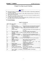
Chapter Five Alarming and Handling
z
Personnel involved in examination and repair must possess corresponding professional
knowledge and abilities.
z
Do not touch driver and motor at least 5 minutes after the power has been cut off for fear of
electric shock and heat injury.
z
After alarm for the failure of drive unit occurs, the unit can only put into operation after the
trouble is shot according to the alarm code.
z
Do confirm that the SON (servo ready) signal is invalid before resetting the alarm for fear that
the sudden staring of motor may cause accidents.
5.1 List of Alarms
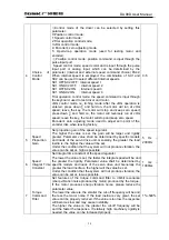
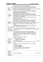
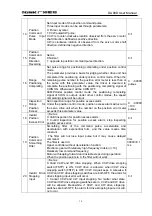
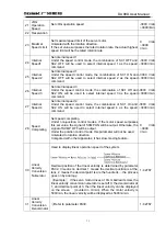
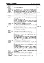
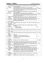
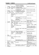
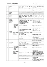
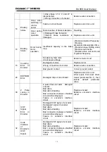
Table 5.1 List of Alarms
Alarm Codes Alarm name
Contents
0 Normal
1
Excessive Speed
Speed of the servo motor exceeds the set value
2
Over-voltage in Main Circuit
Voltage of the main circuit power is excessive
3
Voltage Shortage in Main
Circuit
Voltage of the main circuit power is too low
4
Position Excess
Value in the position error meter surpasses the
set value.
5
Motor Overheating
Excessively high motor temperature
6
Saturation Failure of Speed
Regulator
Long-time saturation of the speed regulator
7
Abnormal Drive Stopping
Both CCW and CW drive stopping are OFF.
8
Overflow of Position Error
Meter
Absolute Value of the number in the position error
meter exceeds 2
30
9
Encoder Failure
Encoder signal error
10
Voltage Shortage in Control
Power
The control power of ±15V is on the low side
11
IPM Module Failure
IPM intelligent module breaks down
12
Excessive Current
Excessive motor current
13
Overload
Overload in servo driver and motor
(instantaneous overheating)
14
Braking Failure
Failure in braking circuit
15
Counting Error of Encoder
Abnormal counting in Encoder
20
EEPROM Error
EEPROM Error
30
Z Pulse Losing in Encoder
Wrong Z pulse in encoder
31
UVW Signal Error in Encoder
Encoder’s UVW signal is wrong or not matchable
with encoder
32
Code Violation of Encoder’s
UVW Signal
or all-low level exists in UVW signal
Attention
Summary of Contents for DA98D
Page 1: ...DA98D Digital AC Servo Drive Unit User Manual V5 00 ...
Page 15: ...DA98D User Manual 4 Fig 1 1 Appearance of Servo Drive unit 2 Servo motor appearance ...
Page 16: ...DA98D User Manual 5 Fig 1 2 Servo Motor Appearance ...
Page 23: ...DA98D User Manual 12 Fig 3 1 Standard Wiring for Position Control Mode AM26LS32 Receiver ...
Page 24: ...DA98D User Manual 13 Fig 3 2 Standard Wiring for Speed Control Mode AM26LS32 Receiver ...
Page 71: ...DA98D User Manual 60 Installation Dimension Drawing for BS 120 Model ...
Page 72: ...DA98D User Manual 61 Installment Dimension Drawing for BS 200 Model ...
Page 73: ...DA98D User Manual 62 Installment Dimension Drawing for BS 300 Model ...
Page 74: ...DA98D User Manual 63 Installment Dimension Drawing for BD 80 Model ...
Page 75: ...DA98D User Manual 64 Installment Dimension Drawing for BD 120 Model ...


