
DA98D User Manual
16
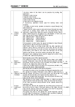
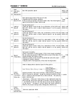
Table 3.2 Control Signal Input/Output Terminal CN1
Terminal
No.
Terminal
Name
Mark I/O
Mode
Functions
CN1-38
CN1-39
Power
Anode of
Input
Terminal
COM+ Type
l
Power anode of input terminal
Used to drive photoelectrical coupler in the input
terminal
DC12
~
24V, current
≥
100mA
CN1-23 Servo
On SON Type1
Servo on input terminal
SON ON: allow driving operation
SON OFF: the driver is closed and stops work; the
motor is under free state
Note 1 before switching SON OFF to SON ON, the
motor must be in stillness;
Note 2: after SON ON is switched on, wait at least
50ms before inputting commands.
CN1-8
Alarm
Stopping
ALRS Type1
Input terminal for alarm stopping
ALRS ON: stop system alarm
ALRS OFF: maintain system alarm
Note1: Alarm for failure code larger than 8 can not
be stopped with this method; it needs to cut off the
power for examination and repair, and then switch
on power.
CN1-24
CCW Drive
Stopping
FSTP Type1
Input terminal for CCW(counter clockwise) drive
stopping
FSTP ON: allow CCW driving operation
FSTP OFF: stop CCW driving operation
Note 1: If limit of the machine is surpassed, the
CCW torque will remain zero when switching on
OFF.
Note 2: The function of FSTP OFF can be
screened off or the function of “ON” can
permanently surface by setting No.20 parameter.
CN1-9
CW Drive
Stopping
RSTP Type1
Input terminal for CW(clockwise direction) drive
stopping
RSTP ON: allow CW driving operation
RSTP OFF: stop CW driving operation
Note 1: If limit of the machine is surpassed, the
CW torque will remain zero when switching on
OFF.
Note 2: The function of FSTP OFF can be
screened off or the function of “ON” can
permanently surface by setting No.20 parameter.
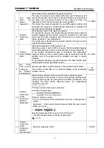
Error Meter
Clearance
CLE Type1 P
Input terminal for clearing position error meter
CLE ON: Position control ; the position error meter
will be cleared
CN1-40
Speed
Choice 1
SC1 Type1 S
Input terminal for speed choice 1
Under the speed control mode, the combination of
SC1 and SC2 can be used to select different
internal speeds
SC1 OFF,SC2 OFF: internal speed 1
SC1 ON,SC2 OFF: internal speed 2
SC1 OFF,SC2 ON: internal speed 3
SC1 ON,SC2 ON: internal speed 4
Note: the values of internal speed 1 to 4 can be
changed with parameters.
Summary of Contents for DA98D
Page 1: ...DA98D Digital AC Servo Drive Unit User Manual V5 00 ...
Page 15: ...DA98D User Manual 4 Fig 1 1 Appearance of Servo Drive unit 2 Servo motor appearance ...
Page 16: ...DA98D User Manual 5 Fig 1 2 Servo Motor Appearance ...
Page 23: ...DA98D User Manual 12 Fig 3 1 Standard Wiring for Position Control Mode AM26LS32 Receiver ...
Page 24: ...DA98D User Manual 13 Fig 3 2 Standard Wiring for Speed Control Mode AM26LS32 Receiver ...
Page 71: ...DA98D User Manual 60 Installation Dimension Drawing for BS 120 Model ...
Page 72: ...DA98D User Manual 61 Installment Dimension Drawing for BS 200 Model ...
Page 73: ...DA98D User Manual 62 Installment Dimension Drawing for BS 300 Model ...
Page 74: ...DA98D User Manual 63 Installment Dimension Drawing for BD 80 Model ...
Page 75: ...DA98D User Manual 64 Installment Dimension Drawing for BD 120 Model ...