background image

2. Installation

PNEG-1813

 Electronic Distributor Control

19

Motor Mounting Bracket Installation

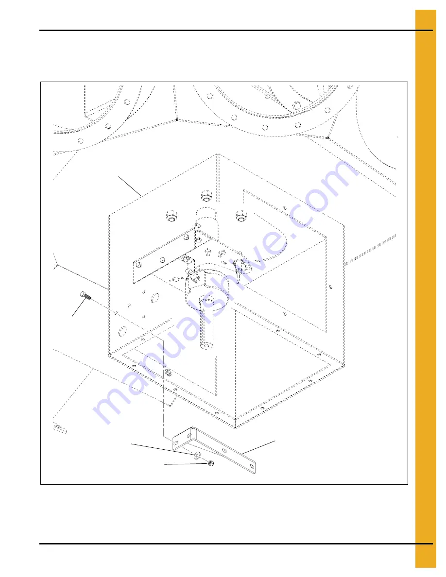
Install the motor mounting bracket (DEC0003) to the enclosure (DEC0005) using two 1/4”-20 x 3/4” HHCS 
bolts (S-1429), 1/4” washers (S-2126), and 1/4”-20 nylock nuts (S-7025) as shown in 

Figure 2K

.

Figure 2K 

Motor Mounting Bracket

1/4” Washer (S-2126)

1/4”-20 Nylock nut 
(S-7025)

1/4”-20 x 3/4” HHCS 
Bolt (S-1429)

Motor mounting 
bracket (DEC0003)

Enclosure (DEC0005)

Summary of Contents for PNEG-1813

Page 1: ...Electronic Distributor Control Installation and Operation Manual PNEG 1813 Date 12 21 20 PNEG 1813 ...

Page 2: ...2 PNEG 1813 Electronic Distributor Control ...

Page 3: ...s 22 Control Panel Cable to Distributor Fitting Connections 23 Motor Cable to Motor Junction Box Fitting Connections 24 Motor Wiring to Motor Junction Box Electrical Connections 25 Control Panel Wiring to Junction Box Electrical Connections 26 Enclosure Covers Installation 27 Control Panel Wiring from Motor Electrical Connections 28 Power Supply Wiring to Control Panel Electrical Connections 29 Co...

Page 4: ...Table of Contents 4 PNEG 1813 Electronic Distributor Control ...

Page 5: ...ions Failure to read this manual and its safety instructions is a misuse of the equipment and may lead to serious injury or death DANGER WARNING CAUTION NOTICE This is the safety alert symbol It is used to alert you to potential personal injury hazards Obey all safety messages that follow this symbol to avoid possible injury or death WARNING indicates a hazardous situation which if not avoided cou...

Page 6: ...e installations are made Follow Safety Instructions Carefully read all safety messages in this manual and safety signs on your machine Keep signs in good condition Replace missing or damaged safety signs Be sure new equipment components and repair parts include the current safety signs Replacement safety signs are available from the manufacturer Learn how to operate the machine and how to use cont...

Page 7: ...ove all jewelry Long hair should be tied up and back Safety glasses should be worn at all times to protect eyes from debris Wear gloves to protect your hands from sharp edges on plastic or steel parts Wear steel toe boots to help protect your feet from falling debris Tuck in any loose or dangling shoe strings A respirator may be needed to prevent breathing potentially toxic fumes and dust Wear har...

Page 8: ...r Control Safety Decals The decals are located as shown below DC 2159 WARNING MOVING PARTS Rotating spout can crush and cut Lock out power before servicing DC 2160 Do not operate with access panel removed Lock out power before servicing CAUTION ...

Page 9: ...tall the shaft DEC0009 to the distributor shaft using two 2 roll pins S 9288 NOTE Flag extension should be installed in line with the spout to ensure proper alignment with the sensor See Figure 2A Figure 2A Electronic Distributor Control Shaft Shaft DEC0009 Flag extension Roll pin S 9288 Spout Distributor shaft ...

Page 10: ...trol Electronic Distributor Enclosure Installation Install the enclosure DEC0005 to the distributor using four 4 3 8 bolts S 7469 and nylock nuts S 7383 See Figure 2B Figure 2B Electronic Distributor Enclosure 3 8 Bolt S 7469 Nylock nut S 7383 Distributor ...

Page 11: ...ox Installation Install the junction box DEC0019 to the enclosure DEC0005 using four self drilling screws S 280 Install the chase nipple washer and locknut See Figure 2C Figure 2C Junction Box Screw S 280 Junction box DEC0019 Locknut Washer Chase nipple Enclosure DEC0005 ...

Page 12: ...nylock nuts S 7025 as shown in Figure 2D Attach the proximity sensor bracket DEC0006 to the inside of the enclosure DEC0005 using three 1 4 20 x 3 4 HHCS bolts S 1429 and 1 4 20 nylock nuts S 7025 See Figure 2D Figure 2D Sensor Plate Angle and Proximity Sensor Bracket Sensor plate angle DEC0014 Proximity sensor bracket DEC0006 1 4 20 x 3 4 HHCS Bolt S 1429 Enclosure DEC0005 1 4 20 x 3 4 HHCS Bolt ...

Page 13: ...e distributor being used and note the proximity sensor reference number This reference number is marked on the bottom of the proximity sensor bracket DEC0006 and identifies the location for installing the proximity sensors DEC0018 Install the two proximity sensors DEC0018 into the proximity sensor bracket DEC0006 at the appropriate locations determined from the table See Figure 2F Figure 2E Proxim...

Page 14: ...2 Installation 14 PNEG 1813 Electronic Distributor Control Figure 2F Proximity Sensor Installation Proximity sensor DEC0018 Proximity sensor bracket DEC0006 ...

Page 15: ...l 15 Proximity Sensor Adjustment Set the clearance of the two proximity sensors DEC0018 to 0 110 0 01 from the face of each sensor to the flag on the shaft DEC0009 See Figure 2G Figure 2G Proximity Sensor Adjustment Proximity sensor DEC0018 Flag 0 110 0 01 ...

Page 16: ... 7223 as shown in Figure 2H Tighten the encoder collar set screw as shown in Figure 2I to 8 in lb Install the encoder mounting bracket DEC0016 to the proximity sensor bracket DEC0006 using the 1 4 20 x 3 4 HHCS bolt S 1429 1 4 washer S 2126 and 1 4 20 nylock nut S 7025 as shown in Figure 2J Figure 2H Encoder to Mounting Bracket Encoder DEC0017 10 32 Bolt S 10167 10 Washer S 7223 Encoder mounting b...

Page 17: ...2 Installation PNEG 1813 Electronic Distributor Control 17 Figure 2I Encoder Collar Set Screw Encoder DEC0017 Encoder collar set screw Encoder collar ...

Page 18: ...13 Electronic Distributor Control Figure 2J Mounting Bracket to Proximity Sensor Bracket Encoder mounting bracket DEC0016 1 4 Washer S 2126 1 4 20 Nylock nut S 7025 1 4 20 x 3 4 HHCS Bolt S 1429 Proximity sensor bracket DEC0006 ...

Page 19: ...ounting bracket DEC0003 to the enclosure DEC0005 using two 1 4 20 x 3 4 HHCS bolts S 1429 1 4 washers S 2126 and 1 4 20 nylock nuts S 7025 as shown in Figure 2K Figure 2K Motor Mounting Bracket 1 4 Washer S 2126 1 4 20 Nylock nut S 7025 1 4 20 x 3 4 HHCS Bolt S 1429 Motor mounting bracket DEC0003 Enclosure DEC0005 ...

Page 20: ... the motor mounting bracket DEC0003 using two 1 4 20 x 1 HHCS bolts S 6998 four 1 4 washers S 2126 and two1 4 20 nylock nuts S 7025 as shown in Figure 2L Figure 2L Control Motor Installation 1 4 Washer S 2126 1 4 20 Nylock nut S 7025 1 4 20 x 1 HHCS Bolt S 1429 Motor DEC0015 Motor mounting block DEC0003 Key DEC0011 ...

Page 21: ...rical fittings For the proximity sensor and encoder cables from the junction box to the control panel use 10 conductor or greater shielded cable 22 AWG or larger and rated for the environment If the wiring is run outside of conduit it should be rated for UV For the motor cable from the motor to the control panel use 4 conductor cable shielded 16 AWG or larger and rated for the environment If the w...

Page 22: ...igure 2M NOTE The grey and red color identifiers indicate the location of the proximity sensors and are shown on the bottom of the proximity sensor bracket DEC0006 Figure 2M Distributor to Junction Box Electrical Connections Proximity sensor DEC0018 Encoder DEC0017 Junction box DEC0019 Junction box terminal block Proximity sensor bracket DEC0006 Blue section Red section Grey section Note Wire colo...

Page 23: ...rol panel to the distributor enclosure DEC0005 and connect the proximity sensors and encoder cable from the control panel to the junction box DEC0019 using suitable fittings See Figure 2N Figure 2N Cable fitting connections to distributor enclosure and junction box Motor cable Junction box DEC0019 Proximity sensors and encoder cable Enclosure DEC0005 ...

Page 24: ... four motor junction box cover screws and the motor junction box cover as shown in Figure 2O Connect the motor cable to the motor junction box using suitable fittings See Figure 2O Figure 2O Cable fitting connection to motor junction box Motor junction box Motor cable Motor junction box cover screws Motor junction box cover ...

Page 25: ...Electrical Connections Connect the motor wiring to the motor wiring terminal block as shown in Figure 2P and re install the motor junction box cover and screws Figure 2P Control panel wiring to motor electrical connections Wire W Wire V Wire U Ground wire Motor cable Motor wiring terminal block ...

Page 26: ...19 terminal block as shown in Figure 2Q NOTE The grey and red color identifiers indicate the location of the proximity sensors and are marked on the bottom of the proximity sensor bracket DEC0006 Figure 2Q Control Panel Wiring to Junction Box Electrical Connections Junction box DEC0019 Junction box terminal block Blue section Red section Grey section Note Wire colors for reference only ...

Page 27: ... 20 x 3 4 HHCS bolts S 1429 and 1 4 lock washer S 2041 each and install the bottom enclosure cover DEC0013 using ten 1 4 20 x 3 4 HHCS bolts S 1429 and 1 4 lock washers S 2041 as shown in Figure 2R Figure 2R Enclosure Covers Installation 1 4 20 x 3 4 HHCS Bolt S 1429 1 4 Lock washer S 2041 Bottom enclosure cover DEC0013 Side access cover DEC0012 ...

Page 28: ...Panel Wiring from Motor Electrical Connections Connect the motor wiring to the motor power terminal block in the control panel as shown in Figure 2S Figure 2S Control panel wiring from motor electrical connections Wire U Wire W Wire V Ground wire Ground terminal block ...

Page 29: ...ough the control panel using suitable hardware as shown in Figure 2T Connect the power supply hot wires to the control panel circuit breakers as shown in Figure 2T Connect the power supply ground wire as shown in Figure 2T to the ground terminal block shown in Figure 2S Figure 2T Control panel wiring from motor electrical connections Power supply ground wire Power cable hardware Control panel circ...

Page 30: ... mount the control panel immediately beside or above heat generating equipment or directly below water or steam pipes The atmosphere surrounding the control panel must be free of combustible vapors chemical fumes and corrosive materials The location of the control panel and the routing of cables should provide safe access for maintenance and suitable operation of the control panel Mount the contro...

Page 31: ...distributors which may result in differences between this manual and that of your actual display Main Screen Depending on the number of spouts in your current configuration one of the following screens will be displayed See Figure 3B The name of the current spout is indicated at the top of the screen and is indicated in the graphic with a green circle At the bottom of the screen are three buttons ...

Page 32: ...ault Displays the Movement Fault screen which offers possible causes and solutions to faults caused by distributor movement See Figure 3D on Page 33 Home Prox Fault Displays the Home Sensor Fault screen which offers possible causes and solutions to faults caused by a proximity switch failure See Figure 3E on Page 33 Drive Fault Displays the VFD Fault screen which offers possible causes and solutio...

Page 33: ...3 Operation Procedures PNEG 1813 Electronic Distributor Control 33 Movement Fault Screen Figure 3D Movement Fault Screen Home Prox Fault Screen Figure 3E Home Prox Fault Screen ...

Page 34: ...3 Operation Procedures 34 PNEG 1813 Electronic Distributor Control Drive Fault Screen Figure 3F Drive Fault Screen ...

Page 35: ...igure 3G 2 On the Move Position screen select the position you want the spout to move to by pressing the spout name on the screen 3 The Main Menu screen will now display a flashing message Moving to at the top of the screen the selected spout number will flash yellow while the pointer is moving to the selected spout The destination spout number will turn green when the move is complete Verifying S...

Page 36: ...oned Setup Menu Screen Figure 3H Setup Menu Screen Configuration Setup Displays the machine setup screen that allows the user to change the distributor s parameters or reload default values See Configuration Setup Screen on page 37 Position Names Allows the user to assign or change the name of each spout position and to create or change a name for the distributor See Position Names Screen on page ...

Page 37: ...and the number of spouts available for that diameter will be displayed Number of Spouts Press the button that matches the current configuration of your distributor The number that is selected will turn green The number of spout options will change according to the diameter of spout selected Reload Defaults If during operation any configuration parameters are altered from the original settings pres...

Page 38: ...e distributor discharge spouts and is also used to create or modify a distributor name Figure 3K Create Modify Spout Names Create Modify Spout Name 1 From the Setup Menu select Position Names to bring up the Create Modify Spout Names screen 2 Press the spout name to be modified to display an alphanumeric keypad See Figure 3L Figure 3L Alphanumeric Keypad ...

Page 39: ...return to Setup Menu Create Modify Distributor Name 1 From the Setup Menu select Position Names to bring up the Create Modify Spout Names screen 2 Next to ochre Distributor Name label press the distributor name to display an alphanumeric keypad See Figure 3L 3 Type in the desired name for distributor press enter 4 Select OK to return to Setup Menu ...

Page 40: ...dividually or an offset can be used to adjust all spouts by the same amount Figure 3M Modify Spout Positioning Modify Spout Positioning 1 From the Setup Menu select Position Locations to bring up the Modify Spout Positioning screen 2 In the Modify Spout Positioning screen select the spout that requires adjustment by touching the value pad next to the spout number balloon A number keypad will displ...

Page 41: ...ge 35 Offset All 1 From the Setup Menu select Position Locations to bring up the Modify Spout Positioning screen 2 In Modify Spout Positioning screen select the 0 key pad next to OFFSET ALL A number keypad will display See Figure 3O Figure 3O Number Keypad 3 Insert the desired offset value and press enter To offset the spouts to the left use a positive value and to offset to the right use a negati...

Page 42: ...nu select Position Lock out to display the Lock Unlock Position setup screen 2 Press name of spout to toggle between locked and unlocked When in the locked position the number balloon will change to a red circle with a line through it NOTE The position that the distributor is currently located indicated by a green number balloon icon can not be locked out Move the spout position to a different loc...

Page 43: ... value of this number the greater the positioning accuracy A default value of 50 is standard Figure 3Q Homing Interval Screen Setting Homing Interval 1 To access the homing interval from the Setup Menu select Homing Interval to display the Homing Interval setup screen 2 Press the button under the Homing Interval label A number keypad will display See Figure 3O Figure 3R 3 Insert the desired interv...

Page 44: ...e is completed The user will be given two options Home Now and Home Next Move Figure 3S Homing Warning Home Now Select to perform the homing calibration immediately The user interface will return to the MAIN screen and Homing will flash on and off in yellow After homing is complete the spout will return to the selected position Home Next Move Select Home Next Move to skip the homing operation and ...

Page 45: ... allows for manually moving the spout in the direction you turn the dial when the key is inserted It is recommended that two people perform this procedure One person to operate the manual jog dial and another to look through the distributor and verify alignment of the spout NOTE Panel will not close with key inserted in the manual jog dial Always keep key in a safe location for access by authorize...

Page 46: ...3 Operation Procedures 46 PNEG 1813 Electronic Distributor Control NOTES ...

Page 47: ...PNEG 1813 Electronic Distributor Control 47 4 Parts Distributor Assembly ...

Page 48: ...4 Parts 48 PNEG 1813 Electronic Distributor Control NOTES ...

Page 49: ...To exit without changes select CLOSE and then OK Reason This message is displayed as you enter the Configuration Setup screen Message The Home proximity sensor was not detected The homing process failed Please check for proper operation of the sensor Reason This error is displayed when attempting to perform a Homing operation and the controller fails to receive a proximity sensor signal before the...

Page 50: ...Reason This error displays when trying to perform a move while bucket elevator is running Remedy Stop bucket elevator before performing spout move Message You cannot lockout this position because it is currently in use Move the spout to a different position and then lockout this position Reason This error displays when trying to lock out a spout position that is in use Remedy Move spout to a diffe...

Page 51: ...s error displays when trying to choose a spout position that is locked out Remedy Select a different position Message The spout has drifted out of position Please verify current position of the spout Reason This error occurs when spout position reading changes without a move command being issued Remedy Check mechanical components for looseness wear or damage Repair or replace as necessary ...

Page 52: ...5 Troubleshooting 52 PNEG 1813 Electronic Distributor Control NOTES ...

Page 53: ...PNEG 1813 Electronic Distributor Control 53 6 Schematic and Wiring Diagrams White Panel Layout ...

Page 54: ...6 Schematic and Wiring Diagrams 54 PNEG 1813 Electronic Distributor Control White Panel Electrical Schematic ...

Page 55: ...6 Schematic and Wiring Diagrams PNEG 1813 Electronic Distributor Control 55 White Panel Electrical Schematic Continued ...

Page 56: ...6 Schematic and Wiring Diagrams 56 PNEG 1813 Electronic Distributor Control NOTES ...

Page 57: ... DESIGN OF SUCH PRODUCTS The sole and exclusive remedy for any claimant is set forth in this Limited Warranty and shall not exceed the amount paid for the product purchased This Warranty only covers the value of the warranted parts and equipment and does not cover labor charges for removing or installing defective parts shipping charges with respect to such parts any applicable sales or other taxe...

Page 58: ...e regulations which should be carefully followed in all cases Authorities having jurisdiction should be consulted before installations are made GSI Group 1004 E Illinois St Assumption IL 62510 0020 Phone 1 217 226 4421 Fax 1 217 226 4420 www gsiag com Copyright 2011 by GSI Group Printed in the USA ...

Reviews: