background image

22

PNEG-1421

     Direct Gear Drive Bin Sweep Auger

INSTALLATION

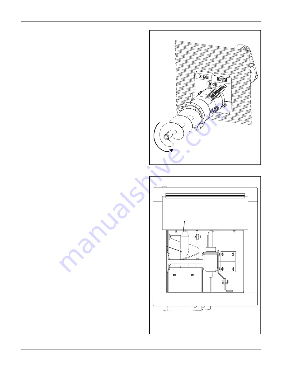
9. Installing the Unload Tube

Flight

A. Begin by removing the tube end cap if you have not

already done so.

B. Insert the Flight into the tube with the square bushing

end facing the center well and the round bushing end
facing the discharge end of the tube. (See Figure 9-A)

C. When the flight is approaching the clutch shaft it will be

necessary to rotate flighting counter-clockwise in order
to get it to seat properly on the squared clutch shaft.
When the flight is properly seated the flight should be
entirely inside the unload tube.  It may be necessary to
pull the flight out a small amount and attempt this step
multiple times in order to seat the flight properly. (See
Figure 9-B)

D. On the initial install with an empty bin, the installer

might want to open the center well and enter the bin to
check and see that the flight is seated.  Once they have
seen that it has seated they will know the proper
position the flight is in on the discharge end when it has
seated properly. (See Figure 9-A)

Fig. 9-A

Fig. 9-B

Clutch Shaft

Flight

Summary of Contents for PNEG-1421

Page 1: ...PNEG 1421 Direct Gear Drive Bin Sweep Auger Direct Gear Drive Bin Sweep Auger PNEG 1421 6 15 06 Assembly Operation Manual with Roller Wells with Roller Wells PNEG 1421 DATE 6 15 06...

Page 2: ...6 8 10 Dia DGD Sweep DGD Sweep DGD Sweep 15 GPS61503 GPS81503 18 GPS61803 GPS81803 21 GPS62103 GPS82103 24 GPS62403 GPS82403 GPS10242 27 GPS62703 GPS82703 GPS10272 30 GPS63003 GPS83003 GPS10302 33 GP...

Page 3: ...Tube Installation 16 17 Bin Flange Instructions 18 Center Well Slide Gate Assembly 19 Control Lever Instructions 6 Systems 19 Rack Pinion Instructions 8 10 Systems 20 Clutch Control Instructions 21 Un...

Page 4: ...r s claim from the Transport Firm THIS MANUAL SHOULD BE CONSIDERED a permanent part of your equipment and should be easily accessible when needed WARRANTY is provided as part of the company s support...

Page 5: ...pment and may lead to serious injury or death SAFETY GUIDELINES DANGER indicates an imminently hazardous situation which if not avoided will result in death or serious injury This is the safety alert...

Page 6: ...ions are made Safety Instructions OPERATE UNLOAD EQUIPMENT PROPERLY Make sure ALL equipment is locked in position before operating NEVER start equipment until ALL persons are clear of the work area Be...

Page 7: ...nd any part of this manual and need assistance contact your dealer Read and Understand Manual INSTALL OPERATE ELECTRICAL EQUIPMENT PROPERLY To avoid serious injury or death stay away from unit and mak...

Page 8: ...e to the job Safety glasses should be worn at all times to protect eyes from debris Wear gloves to protect your hands from sharp edges on plastic or steel parts A respirator may be needed if a hog hou...

Page 9: ...incompetent persons are to remain out of work area 4 O S H A Occupational Safety Health Administration regulations state At the time of initial assignment and at least annually thereafter the employer...

Page 10: ...its SAFETY 1st program Should you ever need guards shields safety decals or owner operator manuals simply contact us and we will supply you with them FREE OF CHARGE While it is our main goal to be the...

Page 11: ...34 AUGER TUBE 6 8 Control Rod Location Control for Intermediate Well Gates Pull To Open I Control for Center Well Gate Pull to Open OUTER ROD NNER ROD 10 Control Rod Location Control for Intermediate...

Page 12: ...there Please remember safety signs provide important safety informa tion for people working near bin unloading equipment that is in operation If the Safety Sign cannot be easily read for any reason o...

Page 13: ...69 10 Wells 6 8 Wells 12 750 15 250 10 Wells 2 275 6 8 Wells 2 750 10 Wells 21 75 28 25 FIG 1 CONCRETE TRENCH LAYOUT FOR 6 8 10 POWER SWEEPS The company does not recommend setting the Direct Gear Driv...

Page 14: ...installed for better access to components under the floor 1 Locate the center of the bin and make a cut out in the bin floor for the center well See Fig 2 A for cut out size and location of 6 8 wells...

Page 15: ...E DISTANCE FROM CENTER BETWEEN CENTER WELL OF BIN TO AND FIRST WALL A INTERMEDIATE WELL B 15 1 7 5 1 2 39 375 9 5 18 1 8 11 7 16 36 75 11 5 21 2 10 5 5 16 32 5 49 75 12 5 24 2 11 11 1 4 38 5 55 75 13...

Page 16: ...ation 13 hole approximately 6 below the bin floor inline with the Center Well Tube 11 hole approximately 6 1 5 below the bin floor inline with the Center Well Tube 9 hole approximately 7 1 2 below the...

Page 17: ...y positioned over both the unload tube and the center well tube Position the connecting band so that it will not interfere with the control rods See figure 4 F F Secure the connecting band with three...

Page 18: ...the bin wall opening is large enough for the clutch and well control rods to pass through the bin wall D Slide the bin flanges flush up to the bin wall and tighten the bolts connecting the two flanges...

Page 19: ...on the TOP side of the center well gate 7A Control Lever Installation 6 Systems 1 Close all slide control gates keep them closed 2 Attach the control lever by sliding the safety snap on pin through th...

Page 20: ...sure the collar faces the gears Fasten down with 3 8 flat washer and 3 8 x 3 4 hex bolt See Figure 7 C 5 With Rack Pinion fully extended attach lower half band and secure to unload tube with six 6 5 1...

Page 21: ...nter well using a 5 16 x 1 3 4 long bolts and lock nut See Figure 8 C C Attach clamp to the control pipe by sliding 5 16 x 1 3 4 long roll pin through the clamp and control pipe Fasten the clamp handl...

Page 22: ...order to get it to seat properly on the squared clutch shaft When the flight is properly seated the flight should be entirely inside the unload tube It may be necessary to pull the flight out a small...

Page 23: ...ure 10 A B Attach the U joint 1 Slide the u joint onto the top gear box output shaft 2 Secure the u joint using a 5 16 x 2 roll pin See Figure 10 B C Install the Pivot Bracket 1 Attach the Pivot Brack...

Page 24: ...5 10 1 8 6 1 7 4 1 8 6 1 8 6 1 8 10 1 4 4 1 7 0 1 7 4 1 7 0 2 7 4 Lengths 24 39 42 48 of Flighting and Shields Required 27 30 33 36 Bin Size 6 Two 2 7 16 x 2 1 2 Bolts 8 Two 2 1 2 x 3 Bolts 10 Two 2...

Page 25: ...ighting shield to the hanger bracket when applicable using two 2 3 8 x 3 carriage bolts flat washers and lock nuts See Figure 10 I 4 Install shield splice brackets to back side of flighting shields us...

Page 26: ...t in the wheel shaft with the hole in the bushing and insert the shaft into the bushing Connect them all together using a 3 8 x 2 1 2 grade 8 HHCS bolt for 6 and a 3 8 x 3 grade 8 HHCS bolt for 8 10 a...

Page 27: ...rols outside the bin but near the bin door so the operator has full view of the operation inside the bin 5 Disconnect power before resetting motor overloads 6 Reset and motor starting controls must be...

Page 28: ...ells 14 Perform Pre start Checks Failure to perform any or all of these pre start checks may cause damage to the equipment and or cause SERIOUS INJURY or DEATH to those in the work area Failure to per...

Page 29: ...both the intermediate and center well control rods as shown in fig 15 C The remaining grain should look similar to fig 15 A 6 Gradually open gates using the middle pivot slot until the desired flow o...

Page 30: ...is established It shouldn t be necessary to open gate more than 3 to 6 4 Always close the center well gate and allow the unloader to clean out before stopping the unloader 5 When grain flow stops fro...

Page 31: ...et Screw and pull on Clutch Control Handle to engage clutch See Figure 16 C Once engagement is felt tighten the Lock Collar Set Screw to hold the clutch engaged D Fully open the Center Well ONLY E Res...

Page 32: ...in will have been removed 4 Stop the equipment and lock out 5 Scoop and sweep by hand the remaining floor area to the center of the bin See Fig 17 B 6 Get out of the bin 7 Repeat steps 3 4 5 and 6 unt...

Page 33: ...o may cause damage This type of damage is considered a misuse of the equipment Any misuse of the equipment may void the warranty 4 Reconnect and unlock the power source 5 Clear the auger gradually unt...

Page 34: ...s equipment may also be a misuse of the equipment Any misuse of the equipment may void the warranty C Use caution when repairing or replacing equipment parts A The u joint must be lubricated with SAE...

Page 35: ...ntake should be covered with grain for maximum capacity B The auger is moving too slowly B1 Check the auger speed Low capacity will result from speeds slower thanrecommended 3 The auger plugs A The au...

Page 36: ...here is room for the auger to move Adjusting the shield may be necessary B Worn sweep wheel B1 The sweep wheel wears down over time Replace the wheel C Unconditioned grain C1 Moisture and or insects c...

Page 37: ...37 PNEG 1421 Direct Gear Drive Bin Sweep Auger PART LISTS PARTS SECTION...

Page 38: ...Flat Washer Zinc 24 S 7382 5 16 Nylock Lock Nut Zinc Grade 5 Center Well Parts 1 2 15 16 17 Ref Part Description 25 GK1704 5 Return Spring 26 S 7149 5 16 18 x 1 3 4 HHCS Bolt Zinc Grade 5 Cover Plate...

Page 39: ...39 PNEG 1421 Direct Gear Drive Bin Sweep Auger PART LISTS Center Well Parts...

Page 40: ...Top Flange GK6757 6 GK6760 8 GK6763 10 Control Rod Guide GK6713 6 GK6711 8 GK6714 10 GC00174 Control Gate Clamp with Dimple for 6 and 8 GC09006 Control Pipe Clamp w Dimple for 10 7 GC03064 Polyuretha...

Page 41: ...8 X 156 75 21 BIN GK7030 8 X24 BIN 12 WELL GK6902 8 X 174 75 24 BIN GK7031 8 X27 BIN 12 WELL GK6903 8 X 192 75 27 BIN GK7032 8 X30 BIN 12 WELL GK6904 8 X 210 75 30 BIN GK7033 8 X33 BIN 12 WELL GK6905...

Page 42: ...560 10 Bottom Bin Flange GC10547 6 GC10536 8 GC10558 10 3 GK1619 Clutch Flange 6 8 10 4 S 3611 5 16 18 Flange Whizz Nut Zinc 5 S 2741 5 16 18 x 1 1 2 HHCS Bolt Zinc Grade 8 6 S 6076 5 16 18 x 3 4 Carr...

Page 43: ...840 OD x 16 GK1749 30 840 OD x 14 6 GC09115 1 OD x 11 8 726 GC10355 GC11120 840 OD x 17 6 GK1754 33 840 OD x 16 GC09116 1 OD x 14 1 664 G10354 GC11121 840 OD x 19 6 GK1761 36 840 OD x 17 6 GC09117 1 O...

Page 44: ...10DP 1 Face 22 Teeth 6 GK6841 Rack Pinion Spacer Tube 7 GK4211 1 Flat Washer 8 GK6845 Rack Pinion Crank Shaft 9 S 4377 2 x 5 16 Pin Spring Half Band GK1603 8 GK5116 10 11 S 2741 5 16 x 1 1 2 18 HHCS...

Page 45: ...45 PNEG 1421 Direct Gear Drive Bin Sweep Auger PART LISTS 8 Rack Pinion 10 Rack Pinion 3...

Page 46: ...eldment 2 GK4538 6 x 8 10 Shield Assembly 3 GK2107 4 GK1678 5 GK1736 6 GK5615 7 GK1266 8 S 4377 9 S 8317 10 S 7372 11 S 7383 12 S 248 13 S 8055 14 S 4275 15 S 1937 16 S 3611 17 S 2086 5 16 Flat Washer...

Page 47: ...eldment 2 GK4745 8 10 x 8 10 Shield Assembly 3 GK1954 4 GK5929 5 GK1951 6 GK5615 7 GK1266 8 S 4377 9 S 8315 10 S 8252 11 S 7383 12 S 248 13 S 8055 14 S 4275 15 S 1937 16 S 3611 17 S 2086 5 16 Flat Was...

Page 48: ...g with Bushing 10 GK4232 1 Bearing with 2 Hole Flange 11 GK4233 Chain Roller 40 Double with Link 12 GK4234 40 Tooth Sprocket with Hub GK4209 14 GA Spacer Plate 6 GK4226 14 GA Spacer Plate 8 10 GK4208...

Page 49: ...49 PNEG 1421 Direct Gear Drive Bin Sweep Auger PART LISTS Reduction Wheel Parts...

Page 50: ...50 PNEG 1421 Direct Gear Drive Bin SweepAuger NOTES...

Page 51: ...DUCTS GSI SHALL NOT BE LIABLE FOR ANY DIRECT INDIRECT INCIDENTAL OR CONSEQUENTIAL DAMAGES INCLUDING WITHOUT LIMITATION LOSS OF ANTICIPATED PROFITS OR BENEFITS PURCHASER S SOLE AND EXCLUSIVE REMEDY IS...

Page 52: ...es and applicable regulations which should be carefully followed in all cases Authorities having jurisdiction should be consulted before installation occurs The GSI Group 1004 East Illinois Street Ass...

Reviews: