Allgemeiner Teil / General Section
TVR 3710 …, TVR 5100 …, TVR 5500 …
1 - 10
GRUNDIG Service
1.3 Removing the Video Unit
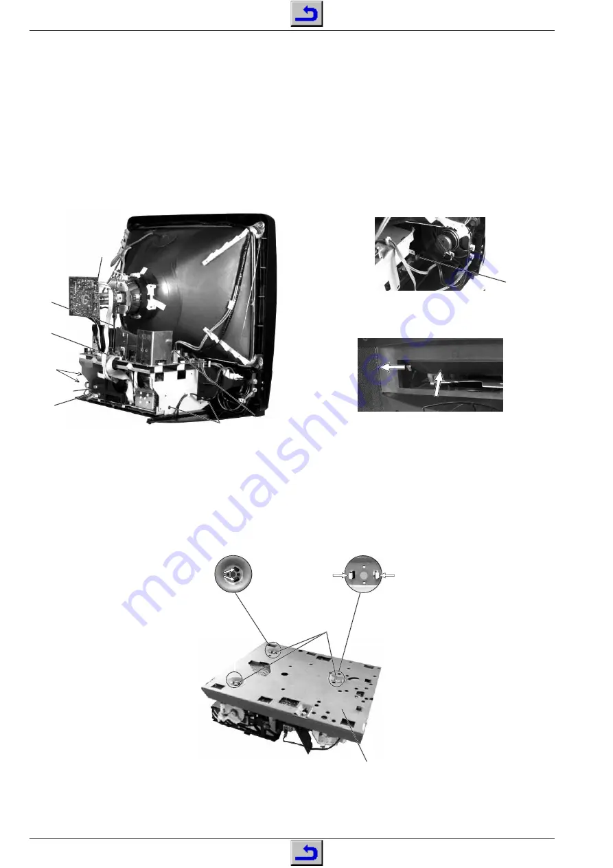
– Undo 4 screws (Pos. 12, Fig. 6).
– Unplug the connectors 1921, 1922 and 1923 (Fig. 6) on the Power
Chassis.
– Unplug the connector 1967 (Fig. 6) on the Tube PCB.
– Push the Power Chassis and the Video Unit towards the back of the
TVR so that the connector 1918 on the Signal Chassis (Fig. 7) is
accessible.
Unplug the connector 1918 from the Signal Chassis.
– Pull out the connector 1971 (option) from the Signal Chassis (Fig. 6).
– Unplug the loudspeaker connectors 1914 and 1970 (option, Fig. 6).
– Raise the Video Unit carefully by a small amount and take it out
towards the back.
Note on re-assembling: When pushing the Video Unit into the TVR
push the cassette flap inwards so that the lever is in front of the
cassette flap (Fig. 8).
1.3 Videoteil ausbauen
– 4 Schrauben (Pos. 12) entfernen (Fig. 6).
– Stecker 1921, 1922 und 1923 (Fig. 6) vom Leistungs-Chassis
abziehen.
– Stecker 1967 (Fig. 6) von der Bildrohrplatte abziehen.
– Leistungs-Chassis und Videoteil mit Montageträger so weit zur
Geräterückseite schieben, daß der Stecker 1918 (Fig. 7) auf dem
Signal-Chassis zugänglich ist.
Stecker 1918 vom Signal-Chassis abziehen.
– Stecker 1971 (Option) vom Signal-Chassis abziehen (Fig. 6).
– Lautsprecherstecker 1914 und 1970 (Option) abziehen (Fig. 6).
– Videoteil vorsichtig anheben und nach hinten herausziehen.
Hinweis zum Zusammenbau: Beim Einschieben des Videoteils in
das Gerät ist die Cassettenklappe so nach innen zu drücken, daß
der Hebel vor der Cassettenklappe ist (Fig. 8).
20
Fig. 9
31
1.3.1 Laufwerk ausbauen
– Steckverbindungen zwischen Signal-Chassis und Laufwerk lösen.
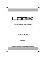
– 3 Schrauben (Fig. 9, Pos. 31) herausdrehen.
– Rastnasen der Laufwerkhalter ausrasten (Fig. 9).
– Abschirmblech (Pos. 20) mit dem Signal-Chassis abnehmen.
1.3.1 Removing the Drive Mechanism
– Unplug the connections between the Signal Chassis and the drive
mechanism.
– Undo 3 screws (Fig. 9, Pos. 31).
– Release the locking lugs of the drive mechanism holders (Fig. 9).
– Remove the metal screen (Pos. 20) together with the Signal Chassis
Fig. 6
Fig. 8
1967
1924
12
12
1921
1922
1923
!
Fig. 7
1918
1925
1971
(Option)
1914
1970
(Option)


