background image

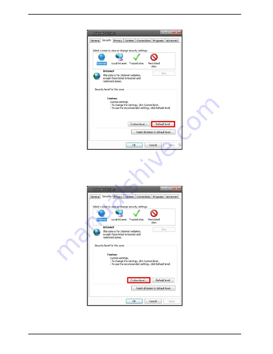
Step 4: Down the page, click on “Default level…” and then click “OK” to confirm the setting. Close the browser 
window, and open a new one later when accessing the IP Camera.

ActiveX Controls and Plug-in Settings :

Step 1~3: Please refer to the previous section above.

Step 4: Down the page, click on “Custom level…” (see the picture below) to change ActiveX controls and plug-in 
settings.

81

English

Summary of Contents for GCI-H0503B

Page 1: ...GCI H0503B 11 1 15 09 2011 Owner s Manual ASP AG IP Cameras Domes GCI H0503B 720P HD IP Col B W Camera WDR Low Light GCI H0602B 720P HD IP Colour Camera GCI K0503B 1080P Full HD IP Col B W Camera...

Page 2: ......

Page 3: ...og File 52 16 View User Information 53 17 View Parameters 55 18 Factory Default 55 19 Software Version 56 20 Software Upgrade 57 21 Maintenance 58 10 Streaming Settings 59 1 Video Format 59 2 Video Co...

Page 4: ...ortant Safety Instructions Be sure to use only the standard adapter that is specified in the specification sheet Using any other adapter could cause fire electrical shock or damage to the product Inco...

Page 5: ...LINE IN MIC IN Two way audio transmission 2 Power LED Green light indicates good power connection 3 Reset Button Press and hold the button for 5 seconds and then the camera will reset to factory defa...

Page 6: ...ounting C CS Mount Lens Model It is possible to attach all CS Mount lenses with manual or DC controlled iris on the camera Please remove the camera s plastic covering first and then attach the CS Moun...

Page 7: ...Camera directly to the PC Check the status of the link indicator and the activity indicator LEDs if the LEDs are unlit please check the LAN connection Green Link Light indicates good network connectio...

Page 8: ...d or Remove Programs In the Currently installed programs list select GRUNDIG Viewer and click the button Remove to uninstall the existing GRUNDIG Viewer as shown in the figure below Deleting Temporary...

Page 9: ...STEP 2 Click on Delete in the first pop up window Then tap Delete Files in the Temporary Internet files section in the next pop up window 7 English...

Page 10: ...ouble click on the program GRUNDIG Finder exe see the desktop icon below its window will appear as shown below Then click on the Find Device button Step 2 The security alert window will pop up Click U...

Page 11: ...d to alter the administrator s password due to security concerns Please refer to section 9 2 Security for further details Additionally users can change the IP Camera s network property either to DHCP...

Page 12: ...ntification Step 2 The Network Setup page will come out Select DHCP and click on the Apply button at the bottom of the page Step 3 Click on OK in the Note of setting the change Wait for one minute to...

Page 13: ...lick on the Information Bar and select Install ActiveX Control to allow the installation Then the security warning window will pop up Click Install to carry on with the software installation Click Fin...

Page 14: ...e interpreted in chapter 9 System Related Settings Streaming setting The Administrator can configure a specific video resolution video compression mode video protocol audio transmission mode etc in th...

Page 15: ...e that additional equipment will be necessary Speaker button on off Click on the Speaker button to mute activate the audio Snapshot button After clicking this button the JPEG snapshots will be automat...

Page 16: ...nctions are additional in the camera model GCI H0503B with RS 485 Interface Pan Tilt Here you find the settings for the Pan Tilt function Pan Tilt Control Users can implement pan tilt control by first...

Page 17: ...Zoom Adjustment Click on the buttons wide tele to control zoom in out Focus Adjustment Users can adjust the focus manually via the near and far buttons 15 English...

Page 18: ...m tab Each category in the left column will be explained in the following sections NOTE The System configuration page is only accessible by the Administrator 9 1 Host Name System Time Setting Click on...

Page 19: ...will be synchronised with the PC Manual The Administrator can set the date time and day manually Entry format should be identical with the format shown next to the enter fields Sync with NTP server Ne...

Page 20: ...n the new user name and password and click Add to add the new user The user name can have up to 16 characters the password up to 14 characters The new user will be displayed in the user name list A ma...

Page 21: ...Delete to remove it To edit a user pull down the user list and select a user name Click Edit to edit the user s password and privileges NOTE It is required to enter the User password and to select the...

Page 22: ...rtificate or a CA signed certificate for implemention of HTTPS After clicking on the HTTPS tab the HTTPS setting page will be shown as in the figure below NOTE The HTTPS function is not available for...

Page 23: ...under Create self signed certificate and provide the requested information to install a self signed certificate for the IP Camera Please refer to the last part of this section Provide the Certificate...

Page 24: ...CA Certificate Authority Provide the requested information in the Create Dialog Please refer to the section Provide the Certificate Information for more details When the request is complete the subjec...

Page 25: ...ate is returned install it by uploading the signed certificate Provide the Certificate Information To create a Self signed HTTPS Certificate or a Certificate Request to CA please enter the information...

Page 26: ...ation to which the entity identified in Common Name belongs Organisation Unit Enter the name of the organisational unit to which the entity identified in Common Name belongs Common Name Indicate the n...

Page 27: ...ill be allowed denied for the listed IP addresses IPv4 Select Allow or Deny from the drop down list and click the Apply button to determine the IP Filter behaviour Add Delete IP Address Input the IP a...

Page 28: ...ication Authority for the purpose of validating itself Upload the certificate for checking the server s identity Client Certificate Private Key Upload the Client Certificate and Private Key for authen...

Page 29: ...ork there will be a drop down menu with several tabs including Basic QoS SNMP and UPnP In the camera model GCI H0503B there are no sub menu tabs under the menu Network but only certain network setting...

Page 30: ...lease refer to the previous section 6 Accessing the Camera for login with the default IP address If Get IP address automatically is selected after the IP Camera restarts users can search the IP addres...

Page 31: ...ick on Enter IP address This is necessary for network identification Subnet mask It is used to determine if the destination is in the same subnet The default value is 255 255 255 0 Default gateway Thi...

Page 32: ...assign a different port number for each separate service mentioned above IPv6 Address Configuration With IPv6 support users can use the corresponding IPv6 address for browsing Enable IPv6 by checking...

Page 33: ...ork Management Protocol With Simple Network Management Protocol SNMP support the IP Camera can be monitored and managed remotely by the network management system NOTE The SNMP function is not availabl...

Page 34: ...dress of the management server Trap community Enter the community to use when sending a trap message to the management system Trap option Warm start A Warm start SNMP trap signifies that the SNMP devi...

Page 35: ...UPnP component is installed on your computer Please refer to chapter 17 Install UPnP Components for UPnP component installation procedure Enable UPnP port forwarding When UPnP port forwarding is enabl...

Page 36: ...main name so that others can connect to it through this name Enable DDNS Check the item to enable DDNS Provider Select one DDNS host from the provider list Host name Enter the registered domain name i...

Page 37: ...ed protocol where one or more recipients of a message are specified and to whom the message text is transferred The configuration page is shown below Two sets of SMTP can be configured Each set includ...

Page 38: ...rotocol FTP site when motion is detected Users can assign an alarm message to up to two FTP sites The FTP setting page is shown below Enter the FTP details which include server server port user name p...

Page 39: ...ve when the setting is finished NOTE The HTTP function is not available for the camera model GCI H0503B Please also refer to 9 8 Application Send HTTP notification 9 9 Motion Detection for HTTP Notifi...

Page 40: ...ction Alarm Type Select an alarm type Normal close or Normal open that corresponds with the alarm application Alarm Output Define the alarm output signal as high or low for the normal alarm output sta...

Page 41: ...hoose to send an alarm message by FTP and or by E Mail when a motion is detected Upload Image by FTP After selecting this item the Administrator can assign a FTP site and configure various parameters...

Page 42: ...tem the alarm triggered recording will be saved on your Micro SD card NOTE Please make sure the local recording with Micro SD SDHC card is activated so that this function can be implemented See sectio...

Page 43: ...guration has been completed See section 9 5 Mail and 9 6 FTP for further details The pre trigger buffer recording function allows users to check what happened to trigger the alarm The pre trigger buff...

Page 44: ...H0503B File Name Enter a file name into the blank box e g image jpg The uploaded image s file name format can be set in this section Please select the one that meets your requirements Add date time su...

Page 45: ...Window is for defining the motion detection area To change the size of the Motion Detection Window move the mouse cursor to the edge of the frame and draw it outward inward When you move the mouse cur...

Page 46: ...gger the value the more sensitive the detection is Meanwhile when the value is bigger the red horizontal line in the motion indication window will be accordingly lower Time interval sec 0 7200 The def...

Page 47: ...triggered The setting range is from 1 to 99999 seconds Select Upload while trigger is active to record the triggered video until the trigger is turned off Send HTTP notification Check this item selec...

Page 48: ...he time the video analysis will need to determine whether any camera tampering has occurred Defining the Minimum Duration can also be interpreted as defining the Tampering threshold longer duration re...

Page 49: ...The pre trigger buffer time range is from 1 to 3 seconds Select Upload for __ sec to set the recording duration after the alarm is triggered The setting range is from 1 to 99999 seconds Select Upload...

Page 50: ...nsert the Micro SD SDHC card the card information such as the memory capacity and status will be shown in the Device Information section The memory card is successfully installed if its status is show...

Page 51: ...on the Remove button Sort When you click on the Sort button the files in the Recording list will be listed in name and date order NOTE The capital letters A M or R appearing in the very beginning of a...

Page 52: ...of schedule mode are offered Always and Only during time frame You can set up the time frame according to your requirements or you can choose Always to allow the Micro SD SDHC Card Recording to be act...

Page 53: ...tains valid characters such as letters and numbers NOTE Users with the Windows 7 operating system on their PC need to follow the following procedure to be able to use the Snapshot function First you n...

Page 54: ...s adjustment please refer to the iris adjustment procedure in the sub menu Iris Adjustment to adjust the iris 9 15 View Log File Click on the link to view the system log file The content of this file...

Page 55: ...nd their privileges see section 9 2 Security View User Login Information All the users in the network will be listed in the User Information zone as shown below The picture below shows User 4321 This...

Page 56: ...e the Administrator will be able to view each user s privileges As the picture above shows User 1 1 0 1 1 1 0 1 I O access Camera control Talk Listen see 9 2 Security This denotes that the user has be...

Page 57: ...k on this item to view the entire system s parameter setting 9 18 Factory Default The factory default setting page is shown below Follow the instructions to reset the IP Camera to factory default sett...

Page 58: ...estart NOTE The IP address will also be restored to default 192 168 1 1 Reboot When you click on the Reboot button the system will restart without changing the current settings 9 19 Software Version T...

Page 59: ...nary file list and select the file you want to upgrade in this case select userland jffs2 Step 3 Click on Upgrade The system will first check whether the upgrade file exists or not and then begin to u...

Page 60: ...tion for future use When you click on the Export button the File Download window will pop up as shown below Click Save and specify a desired location for saving the configuration file Upload To copy a...

Page 61: ...264 format includes H 264 720p 25fps MJPEG 720p 25fps H 264 720p 25fps MJPEG D1 25fps H 264 720p 25fps MJPEG CIF 25fps H 264 720p 25fps MJPEG VGA 25fps H 264 720p 25fps MJPEG QVGA 25fps For MJPEG BNC...

Page 62: ...0 25 fps 320 x 240 25 fps 352 x 288 25 fps 176 x 144 25 fps Resolution for MJPEG MPEG 4 includes For MJEPEG format and Mpeg 4 format each 1280 x 960 12 5 fps 1280 x 720 25 fps 720 x 576 25 fps 640 x 4...

Page 63: ...s 640 x 480 25 fps 320 x 240 25 fps 352 x 288 25 fps 176 x 144 25 fps Text Overlay Settings Users can select these items to display data date time text on the live video pane The maximum length of the...

Page 64: ...180 degree rotation Selecting the 180 degree rotation will inverse the image 180 counter clockwise Click Save to confirm the setting GOV Settings Users can set the GOV length to determine the frame st...

Page 65: ...y factor A higher value implies higher bit rates and a higher visual quality The default setting is 35 the setting range is from 1 to 70 Click Save to confirm the setting H 264 1 H 264 2 bit rate The...

Page 66: ...It is important to take into account the image quality when you choose to use CBR mode Click on Save to confirm the setting For the camera model GCI H503B users can specify the values for MJPEG H 264...

Page 67: ...4096 kdps default 6144 kdps 8192 kdps lowest compression highest quality The MPEG 4 compression settings include 512 kdps highest compression lowest quality 1024 kdps 10 3 Video OCX Protocol In the Vi...

Page 68: ...ve to confirm the setting 10 4 Video Frame Rate Video frame skipping is for saving bandwidth if necessary The setting page for the camera models GCI H0602B and GCI K0503B is shown below For the camera...

Page 69: ...I H0503B the Frame rate options for MJPEG and MPEG 4 format include 1 fps 5 fps 12 5 fps 25 fps Click Save to confirm the setting The Frame rate options for this camera model for H 264 1 and H 264 2 f...

Page 70: ...model GCI H0503B there are five video masks which can be set by the users For the camera models GCI H0602B and GCI K0503B there are two video masks which can be set by the users The masks are limited...

Page 71: ...hite yellow green blue cyan and magenta Type Select solid or transparent as mask type Click on Save to confirm the setting 10 6 Audio The audio setting page is shown below In the Audio page the Admini...

Page 72: ...s G 726 uLAW G 711 and ALAW G 711 Both uLAW and ALAW signify 64 Kbps but in different compression formats A higher bit rate signifies a higher audio quality and requires a bigger bandwidth Click on Sa...

Page 73: ...plied to Full Auto Flickerless Mode Full Auto Flickerless Mode Television scanning PAL NTSC and power supply systems AC 50 60 Hz are not the same in different countries and regions Therefore users mig...

Page 74: ...75 watt Bulb Colour Temperature 2 820 K Candle Flame Colour Temperature 1 200 to 1 500 K Auto Mode The Auto Balance White mode is suitable for an environment with a light source having a colour tempe...

Page 75: ...arper it especially enhances the object s edges Click on to confirm the new setting 11 6 Contrast Setting The camera image contrast level is adjustable please choose from a range of 6 to 19 Click on t...

Page 76: ...g high contrast or changing light issues to improve the video display The WDR is adjustable from level 1 to 4 A higher level of WDR represents a wider dynamic range so that the IP Camera can catch a g...

Page 77: ...ng pan tilt control please ensure that the Pan Tilt Head is correctly connected to the IP Camera s RS 485 port Pin Definition for the RS 485 Port of this IP camera PIN 1 Output PIN 2 Output PIN 3 Inpu...

Page 78: ...the desired position by moving the mouse cursor onto the screen click on the left mouse button hold it and drag the red arrow to pan tilt the camera Users may adjust the zoom position as well Step 2 O...

Page 79: ...each line please press the Reset button in the top right corner of the setup page Then press the button on the left to refresh the page in order to enter the new settings When finishing the sequentia...

Page 80: ...ons include DSCP 9600 PelcoD 2400 PelcoD 4800 PelcoD 9600 PelcoP 2400 PelcoP 4800 PelcoP 9600 Click Save to confirm the setting Pan Tilt Control Users can implement pan tilt control by first moving th...

Page 81: ...e network via the Video Server into one system Offering powerful functionalities via intuitive interface it is a centralised monitoring solution for your video surveillance equipments The GRUNDIG CMS...

Page 82: ...Internet security level to default or change ActiveX controls and plug in settings Internet Security Level Default Step 1 Start the Internet Explorer Step 2 Select Tools from the main menu of the brow...

Page 83: ...e the browser window and open a new one later when accessing the IP Camera ActiveX Controls and Plug in Settings Step 1 3 Please refer to the previous section above Step 4 Down the page click on Custo...

Page 84: ...tiveX controls 4 Binary and script behaviors 5 Display video and animation on a webpage that does not use external media player 6 Download signed ActiveX controls 7 Download unsigned ActiveX controls...

Page 85: ...rocedure of the GRUNDIG Viewer software download is specified as follows Step 1 In the GRUNDIG Viewer installation page click Next to start the installation Step 2 Setup starts Please wait for a while...

Page 86: ...k on Finish to close the GRUNDIG Viewer installation page Then the IP Camera s Home page will be displayed as follows NOTE Please note that the function buttons may vary depending on the camera model...

Page 87: ...mponents The procedure is for Windows XP for other systems please refer to the corresponding manuals Step 1 Go to Start click on Control Panel and then double click on Add or Remove Programs Step 2 Cl...

Page 88: ...nents list in the Windows Components Wizard window and then click on Details Step 4 Select UPnP User Interface in the Networking Services subcomponents list and then click on OK Step 5 Click on Next i...

Page 89: ...away or as far as possible Please loosen the focus ring s retaining screw with the supplied back focus adjuster Step 2 Make sure the iris is wide open Therefore it is advised to keep the environment...

Page 90: ...om range When using a zoom lens and changing the focal length the focus does not need to be adjusted again once the back focus adjustment has been completed This does not apply to vario lenses Step 8...

Page 91: ...m Event Alarm Input Motion Detection or Schedule Image transfer or alarm message by FTP Image transfer or alarm message by E mail recording on SD card enable alarm output Audio Compression G 726 ADPCM...

Page 92: ...ensitivity 0 2 lux F1 2 Colour 0 02 lux F1 2 B W Video Resolution 1920 x 1080 25 fps 1280 X 720 2x25 fps Alarm Event Alarm Input Motion Detection or Schedule Image transfer or alarm message by FTP Ima...

Page 93: ...e standards in the following relevant provisions EC EMC Directive 2004 108 EC Low Voltage Directive 2006 95 EC Applied harmonised standards and technical specifications EN 55022 Class A 2006 A1 2007 E...

Reviews: