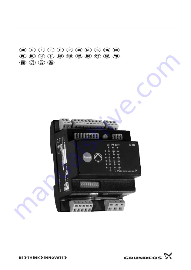
IO 112
GRUNDFOS
INSTRUCTIONS
Installation and operating instructions
Page 1: ...IO 112 GRUNDFOS INSTRUCTIONS Installation and operating instructions...
Page 2: ...os quais se refere esta declara o est o em conformidade com as Directivas do Conselho das Comunidades Europeias relativas aproxima o das legisla es dos Estados Membros respeitantes Material el ctrico...
Page 3: ...siune 2006 95 CEE Standard aplicat EN 61010 1 2001 Compatibilitate electromagnetic 89 336 CEE Standarde aplicate EN 61000 6 2 i EN 61000 6 3 Grundfos IO 112 2006 95 E O EN 61010 1 2001 89 336 E O EN 6...
Page 4: ...direkt v m par tuvin anos EK dal bvalstu likumdo anas norm m Elektriskais apr kojums kas paredz ts lieto anai zin mu sprieguma robe v rt bu ietvaros 2006 95 EEK Piemerotais standarts EN 61010 1 2001...
Page 5: ...driftsinstruktion 124 Asennus ja k ytt ohjeet 137 Monterings og driftsinstruktion 150 Instrukcja monta u i eksploatacji 163 177 Szerel si s zemeltet si utas t s 197 Navodila za monta o in obratovanje...
Page 6: ...IO 112 interface has three inputs for measured values one potentiometer for setting of limits indicator lights indicating the measured value of the input value of the limit set alarm source pump statu...
Page 7: ...r to reduce the external pollution level to maximum 2 the IO 112 must be installed in a pro tecting environment with minimum IPX4 enclosure according to IEC 60529 The cabinet must be of a flame retard...
Page 8: ...a good electric contact from the mounting plate through the mounting screws to the metal cabinet of the frequency con verter Use toothed washers and a galvanically conduct ing mounting plate Fig 5 Scr...
Page 9: ...module See fig 1 The temperature sensor is for instance used for measurement of the liquid temperature or the motor temperature Counter input If switches 1 and 2 are set to counter input CNT IO 112 i...
Page 10: ...ling has been selected the indicator lights will illuminate from the top and downwards as the value falls 7 1 4 Counter input falling rising With DIP switch 5 it is possible to set whether an alarm is...
Page 11: ...Limit 1 and limit 2 With DIP switch 7 it is possible to add limits 1 and 2 to the analog input and the temperature sensor input It is not possible to add the limits to the counter input Switch 6 Descr...
Page 12: ...cator light of the selected input will flash 5 seconds after the limit has been set with the poten tiometer the setting is saved and the indicator light will be off When setting the limits with the po...
Page 13: ...30 illuminates Wait 5 seconds until the value has been stored 8 2 Example 2 draining application The application is controlled by a level sensor The pump must start when the water reaches the maxi mu...
Page 14: ...til the value has been stored 8 4 Example 4 application with falling temperature The application is controlled by a Pt1000 sensor The pump must start when the temperature of for instance a liquid reac...
Page 15: ...os Symbol Description 1 Reset button If the reset button is pressed for less than 3 seconds all alarm indicator lights will go out If the cause of the alarm has not been remedied the indicator lights...
Page 16: ...The limit is not set correctly rising falling Check switch 4 The CNT indicator light is on An alarm has been registered Press the Reset button for less than 3 seconds The alarm limit is not correct Ch...
Page 17: ...be short circuited when the pump is running K2 Terminal for conductor for contactor status Digital input R1 GND connection 0 V For resetting of alarms see section 10 1 The input must be short circuit...
Page 18: ...CNT terminal for alarm output D6 GND for CNT D7 Not in use D8 Not in use Note If the switched voltage is greater than 30 VDC special precautions must be taken Please contact Grundfos Pos in fig 1 Ter...
Page 19: ...level sensor TM03 7807 4906 M U V W 230 VAC L1 L2 L3 24 VAC DC 4 20 mA PE T1 T2 G1 A1 G2 A2 K1 K2 R1 R2 P1 P2 P3 P4 P5 A Y B ON DIP 1 2 3 4 5 6 7 8 9 10 IO 112 Reset 15 90 75 60 45 30 120 100 80 60 4...
Page 20: ...ensor TM03 7809 0607 M U V W 230 VAC L1 L2 L3 24 VAC DC PE T1 T2 G1 A1 G2 A2 K1 K2 R1 R2 P1 P2 P3 P4 P5 A Y B ON DIP 1 2 3 4 5 6 7 8 9 10 IO 112 Reset 15 90 75 60 45 30 120 100 80 60 40 20 600 500 400...
Page 21: ...TM03 7808 0607 M U V W 230 VAC L1 L2 L3 24 VAC DC PE T1 T2 G1 A1 G2 A2 K1 K2 R1 R2 P1 P2 P3 P4 P5 A Y B ON DIP 1 2 3 4 5 6 7 8 9 10 IO 112 Reset 15 90 75 60 45 30 120 100 80 60 40 20 600 500 400 300 2...
Page 22: ...390...
Page 23: ...Shizuoka pref 431 21 Phone 81 53 428 4760 Telefax 81 53 484 1014 Korea GRUNDFOS Pumps Korea Ltd 6th Floor Aju Building 679 5 Yeoksam dong Kangnam ku 135 916 Seoul Korea Phone 82 2 5317 600 Telefax 82...
Page 24: ...www grundfos com Being responsible is our foundation Thinking ahead makes it possible Innovation is the essence 96650446 0307 185 Repl 96650446 0207...