English (GB)
4
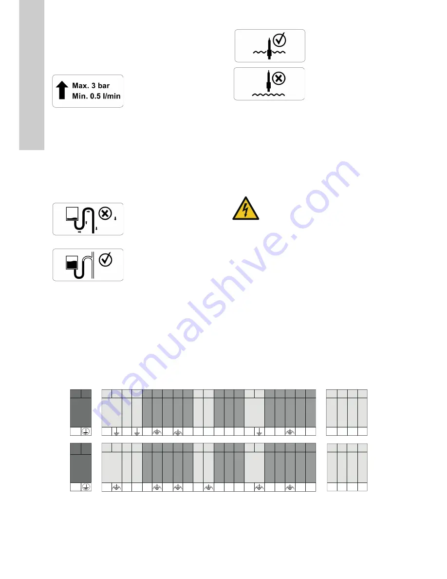
Please note the pressure and flow limitation of the DID as
explained in the technical data on the warning label. Independent
of the inlet discharge the flow within the DID will be reduced by
the flow restrictor to the correct amount.
• Mount the customer outlet tube onto the 1/2" outlet fitting
• Ensure proper layout of the outlet tube to avoid soaking
The tubing on the outlet has to be designed in that way that a
draining of the flow cell is not possible. To ensure this a vented
outlet has to be used. Furthermore no shut-off valve should be
used to avoid back pressure within the flow cell.
• Install strain-relief in case of long / heavy outlet tubes to avoid
mechanical load of the flow cell.
• Due to sealing plugs on in- and outlet, proper 1/2" fittings have
to be mounted by the costumer (part of delivery).
• High loads due to heavy tubes on the outlet port of the flow
cell can damage the mounting of flow cell. Therefore it is
recommended to install a strain-relief for the outlet tubing.
4.4 Installing of sensors
All sensors used in the DID are packed separately to avoid any
damage. They have to be prepared before installation according
to the section Installation in the sensor manual. Within this
manual you will also find a detailed explanation how to mount the
sensors into the flow cell.
As soon as the sensors are ready for operation they should be
wetted all the time. All sensors equipped with electrolyte and
membrane cap have to be powered all the time.
4.5 Checking of tightness
Carefully open the inlet valve on the inlet and check for any
leakage of the DID. Check if any air bubbles are visible within the
tubes and spill them out by temporary increase of the discharge.
5. Starting up the product
5.1 Initial startup
Once the mounting and installation have been completed and
checked, the initial start up of the DID will require the following
actions, in the order presented below:
Described below are the steps that are specific for the DID and
that are not covered in the specific manuals of the sensors
included in your DID. The DID specific actions are to be
performed in the following order:
1. Connect all sensors to the control unit CU 382
2. Open inlet valve slowly
3. Check for leakage in the hydraulic system of the DID
5.2 Terminal connection
Once the cover has been opened (two cross head screws
removed) you have access to the cable terminal compartment of
the control unit CU 382.
Be aware that cable clamps of relay contacts you have connected
to the device might also have power supply (230 VAC),
depending on how they have been interconnected!
Fig. 2
Plan of terminal connections within control unit CU 382
WARNING
Electric shock
•
Switch off the power supply before installing!
Enclosure class IP65 is only guaranteed if the
terminal cover is correctly sealed, if the front
panel of the terminal enclosure is closed and the
appropriate cable glands or dummy caps fitted.
•
This type of work must be carried out by
authorized persons only and after disconnecting
the power supply!
T
M
06
59
58
03
1
6
1 3
5 7 9
RS485
11 13 15 17
21 23 25 27 29 31 33 35 37 39 41 43 45
47 49 51 53
2 4
6 8 10 12 14 16
20 22 24 26 28 30 32 34 36 38 40 42 44 46
48 50 55 54
18
19
12 V Out
GND
4/20 #1
4/20 #2
4/20 #3
4/20 ln #1
4/20 ln #1
ln #1
ln #2
Flow #1
RS485
MOD 1
MOD 1
MOD 2
MOD 2
Relay 1
Relay 2
∑ Err
∑ Err
RS485
Valve
Clean in
4/20 #1
4/20 #2
4/20 #3
4/20 ln #1
ln #1
ln #2
Flow #1
RS485
MOD 1
MOD 1
MOD 2
MOD 2
Relay 1
Relay 2
∑ Err
∑ Err
90...240 V
A
C
90...240 V
A
C
P
A-
A-
PS
+
+
+
+
+ + +
NO NO NO NO
N
B+
B+
-
+
-
-
-
-
-
C C C C
+


