English (GB)
10
9. Operating the product
9.1 Software overview
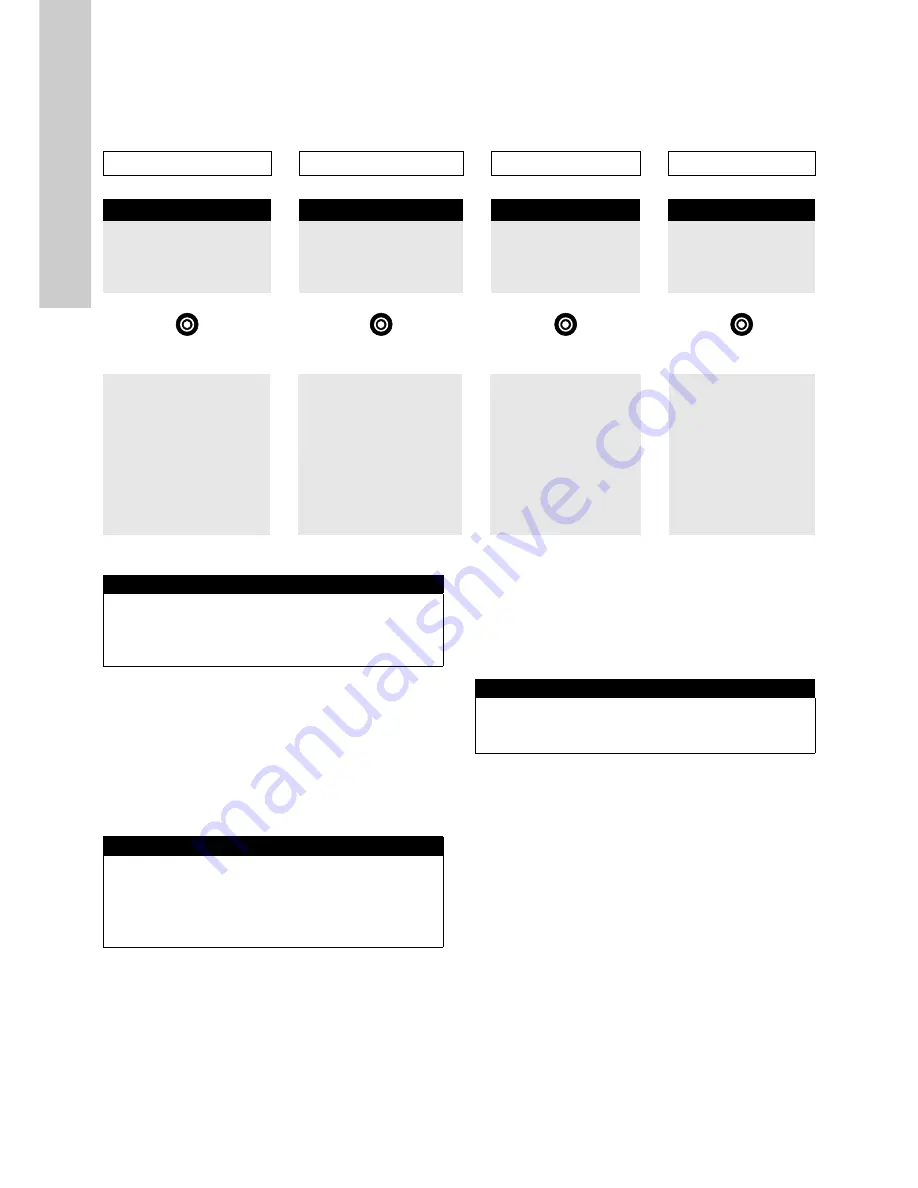
The CU 382 has four different views which can be selected by using [Right]- and [Left]-button. The default screen (i.e. after restart) is the
Parameter screen.
Pressing [Back] button several times (depends on level of sub menu) will always get the user back to one of these screens
9.1.1
.
Status screen
.
The first row shows the version of the software. In case problems
make it necessary to contact our service department, the Status
menu enables the operator to easily identify the software version
(Version) and the serial number (Serial) of the actual device.
The third row (Waiting) shows the waiting time to the next action
(start of measurement or start of cleaning). This interval can be
set in menu Measurement settings (Meas. Settings…).
The last row (YYYY/MM/DD) shows current date and time. This
can be set in menu.
9.1.2 Parameter screen
This is the default parameter screen. It shows two measured
values at once. Besides the reading itself the parameter name
(FCL) and the unit (mg/l) is displayed. The inverted font in the
header displays the selected parameter which is marked with a
triangle symbol. To scroll through the list of configured
parameters use [Up]- and [Down] buttons. Up to 8 parameters
can be configured and therefore displayed.
These displayed parameters can be:
– Sensor reading
– Analog input
– Digital input
– Flow guard
Quick calibration
It is possible to make a quick calibration directly from the
parameter screen.
Choose the parameter you want to calibrate with [Up]- and
[Down] buttons and pressing [OK] button will open up the Quick
calibration menu.
Before taking a sample to perform a calibration, rinse the
sampling point of the flow cell at least 3 times to remove all
residuals from the sampling point. After this, approx. 10 ml should
be analysed by a reference method and the result has to be
entered into field Lab 1.
At the same time the sample is taken, Sample 1 has to be
selected with [Up]- and [Down] buttons and [OK] button has to be
pressed to measure the raw value of this sample. This current
measured raw value will be stored onto the sensor.
As soon as the Sample 1 is measured and the corresponding Lab
1 value has been entered, the calibration can be executed by
selecting Perform Calibration with [Up]- and [Down] buttons and
pressing [OK] button.
The Quick calibration menu will be closed and the new calibration
coefficient will be used for measurement.
Status
Parameter
Controller
Alarm
Status
>
<
∨
P1/3 pH
>
<
∨
C2/2
>
<
AP001 A1/1
Version
V7.05B1
pH
15 %
YYYY/MM/DD
Serial:
9999999
►
9.49
Type
PID/Running
Follow below
Waiting:
1s
Temp.
pH
>4/20 mA #2
lower alarm limit
YYYY/MM/
DD
h/min/sec
22.1
C
AV/SP: 6.86/7.00
(ext.)
General set up
Parameter set up
Controller set up
Alarm set up
►
Manage sensor
►
Calibrate expert
►
Setpoint
►
Acknowledgment of
alarms
Manage parameters
Monitor
Settings PID/2-P/
None
Cleaning 1
Display settings
Source
Measuring settings
Alarm settings
Output DI/mA
Date/Time
Output
Output settings
Modbus slave
Output settings
Alarm settings
Update software
pH compensation
Reset state
Select language
Parameter info
Service
Remove parameter
Status
>
Version: V7.05B1
Serial: 9999999
Waiting: 1s
2015/Oct/05
16:40:49
<
∨
P1/3 FCL
>
0.531
FCL
►
mg/l
7.8
pH
P1 Quick calibration
►
Lab 1:
0.35
Sample 1:
2.41
Perform calibration


