En
gl
is
h (
G
B)
44
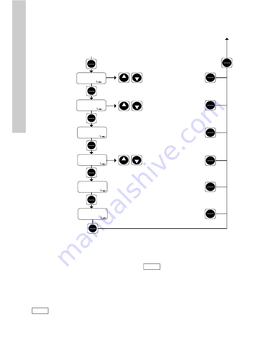
Fig. 43
Second function level, part 2
9.6 Calibration
The dosing flow display is set by default for an
operating counter-pressure of 3 bar. Calibration can
be used to set the pump flow to the actual operating
conditions.
Calibrate the pump under normal operating
conditions with the discharge line connected and at
operating counter-pressure.
TM
03 661
0 450
6
Stop
Start
Stop
Start
1
h
Stop
Start
Down
Up
OFF
9999
OFF
OFF
BUS
SL : OF
Stop
Start
Stop
Start
Stop
Start
Stop
Start
Down
Up
Down
Up
t
B
l /
Menu
Info
Menu
Info
Menu
Info
Menu
Info
Menu
Info
Menu
Info
Menu
Info
Setting code 111
Calibration
Dosing controller
Pressure control
Memory function
Weighting of current input/output
Batch on/off
ON / OFF
Adjustment of batch quantity and
dosing rate for batch operation,
see section
9.6.5 Batch menu /
batch mode
Timer on/off
ON / OFF
Adjustment of batch quantity,
dosing rate and times for Timer,
see section
9.6.6 Timer menu /
timer mode
Slow mode on/off
ON / OFF
To set the slow-mode factor, see
section
9.6.8 Slow mode
Display of total dosing quantity [l] (resettable)
0.000-9.999
10.00-99.99
100.0-999.9
1000-9999
Display of operating time of drive
1 = 10 h to 9999 = 99,990 h
See previous page
Bus address indication
Operating hours
counter
Dosing quantity
counter
PROFIBUS
(only with PROFIBUS)
Slow mode
(anti-cavitation)
Batch
Timer
Note
Due to the small stroke volume of the
DDI 0.4-10, calibration is essential for
a precise dosing flow.
Before calibrating the DDI 0.4-10,
deaerate the pump and then let it run
for 15 minutes at operating
counter-pressure with full stroke rate.
Note
The dosed volume must be gauged in
litres during calibration, e.g. by
drawing the dosing medium from a
gauged tank. (For an alternative for
pumps with Plus
3
system, see section
9.6.1 Calibrating pumps with Plus
3
system (internal calibration)).


