


Automatic Greasing System
TriPlus Trailer
Description components
13
Date of
is
sue :
Sept
e
m
ber
2
012
F212157R02
2.7
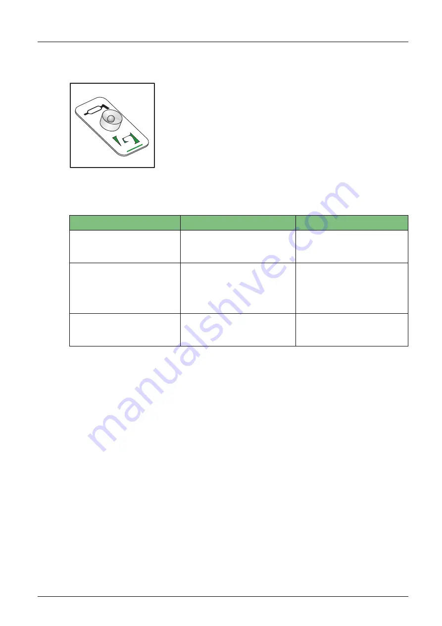
The signal light
The driver or operator will be informed about the operation of the
greasing system through a signal light which is installed on the
dashboard in the cabin. The physical form of the signal light may vary,
but it is always installed so that is easily visible.
Figure 2.4
The signal light
The signal light produces the following signals:
Signal
Moment
Significance
1 x 3 seconds on.
5 seconds after switching on
contact.
The supply voltage for the
control unit is available and
the signal light is OK.
1 x 2 minutes on.
After completion of a pump
phase.
An error occurred during the
pump phase. Precisely which
error occur-red can be deter-
mined by using the test push-
button.
Repeatedly: 1 x 0,3 seconds
on, followed by a pause of 2
seconds.
After momentarily pressing
the test pushbutton once.
A test cycle is being per-
formed via grease output
port 1.
GROENEVELD
976.01
Summary of Contents for TriPlus Trailer
Page 57: ......