Grizzly T31634 Owner'S Manual Download Page 61

Model T31634/T31635 (Mfd. Since 8/19)

-59-

BUY PARTS ONLINE AT GRIZZLY.COM!

Scan QR code to visit our Parts Store.

REF PART #

DESCRIPTION

REF PART #

DESCRIPTION

43

PT31635043

PHLP HD SCR M4-.7 X 12

151

PT31635151

PHLP HD SCR M5-.8 X 16

59

PT31635059

PLASTIC LOCK RING

152

PT31635152

ARMATURE

64

PT31635064

SCREW M6 X 10

153

PT31635153

PHLP HD SCR M5-.8 X 70

68

PT31635068

FLAT WASHER 4MM

154

PT31635154

STATOR

75

PT31635075

COMPRESSION SPRING 1 X 6 X 17

155

PT31635155

BALL BEARING 6001-2RS

76

PT31635076

LOCKING BLOCK

156

PT31635156

BEARING HOUSING

77

PT31635077

CLAMP RELEASE BUTTON

157

PT31635157

CAP

78

PT31635078

CLAMP PLATE

158

PT31635158

CARBON BRUSH

79

PT31635079

FLAT WASHER 4MM

159

PT31635159

BRUSH HOLDER

80

PT31635080

LOCK WASHER 4MM

160

PT31635160

PHLP HD SCR M5-.8 X 45

81

PT31635081

CLAMP AXIS POST

161

PT31635161

MOTOR HOUSING

82

PT31635082

PLATE

163

PT31635163

OPERATING HANDLE (TOP)

83

PT31635083

KNOB BOLT 1/4-28 X 15, 6-LOBE, D26

164

PT31635164

GROMMET 10 ID 20MM OD

84

PT31635084

CLAMP FRAME

165

PT31635165

HANDLE (UPPER)

85

PT31635085

CLAMP POST M12 X 130

166

PT31635166

TAP SCREW M4.2 X 16

90

PT31635090

TAP SCREW M4.2 X 14

167

PT31635167

PHLP HD SCR M5-.8 X 60

100

PT31635100

LOCK WASHER 5MM

168

PT31635168

LASER SWITCH KCD-117

112

PT31635112

BEARING OD 8MM

169

PT31635169

LED LIGHT SWITCH KCD-117

113

PT31635113

EXT RETAINING RING 14MM

170

PT31635170

SCREW CAP

114

PT31635114

WASHER 14MM

171

PT31635171

MOTOR COVER

115

PT31635115

BEVEL GEAR

172

PT31635172

PHLP HD SCR M5-.8 X 35

116

PT31635116

KEY 4 X 4 X 12 RE

173

PT31635173

CONTROLLER ASSEMBLY

117

PT31635117

ARBOR SHAFT

174

PT31635174

COMPRESSION SPRING 1 X 30 X 8

118

PT31635118

GEAR COVER

175

PT31635175

TRIGGER

119

PT31635119

BALL BEARING 6003-2RS

176

PT31635176

RELEASE BUTTON

120

PT31635120

PLATE

177

PT31635177

BUTTON PRESS POST

121

PT31635121

FLAT HD CAP SCR M4-.7 X 10

178

PT31635178

TAP SCREW M2.9 X 10

122

PT31635122

FLAT HD CAP SCR M6-1 X 16

179

PT31635179

COMPRESSION SPRING 1 X 30 X 8

123

PT31635123

DUST CHUTE

180

PT31635180

MICRO SWITCH KEDU WD01-1

124

PT31635124

GUARD ARM

181

PT31635181

TERMINAL BAR 4P

125

PT31635125

FLAT WASHER 6MM

182

PT31635182

TAP SCREW M4.2 X 20

126

PT31635126

DUST BAG CLIP

183

PT31635183

OPERATING HANDLE (BOTTOM)

127

PT31635127

DUST BAG

184

PT31635184

LOCK NUT M5-.8

128

PT31635128

BEARING PIN

185

PT31635185

FLAT WASHER 5MM

129

PT31635129

BALL BEARING 606-2RS

186

PT31635186

FIXED PLATE

130

PT31635130

DUST BAG FRAME

187

PT31635187

BLADE GUARD (LOWER)

131

PT31635131

KNOB BOLT M6-1 X 54, 6-LOBE, D20

188

PT31635188

COTTER PIN M6 X 15 HAIRPIN

132

PT31635132

KNURLED NUT M6-1

189

PT31635189

SCREW M6 X 16

133

PT31635133

BLADE GUARD (UPPER)

190

PT31635190

TORSION SPRING

134

PT31635134

WIRING PROTECTOR

191

PT31635191

SCREW M6 X 12

135

PT31635135

CABLE CLIP

192

PT31635192

COVER PLATE

136

PT31635136

EXT RETAINING RING 11MM

193

PT31635193

CARRIAGE BOLT M5-.8 X 16

137

PT31635137

SHAFT

194

PT31635194

INNER FLANGE

138

PT31635138

COMPRESSION SPRING 0.8 X 8 X 14

195

PT31635195

SAW BLADE 12" X 48T X 1" ARBOR

139

PT31635139

LASER, CLASS II, 3V, 400-700NM

196

PT31635196

OUTER FLANGE

140

PT31635140

SET SCREW M6-1 X 6

198

PT31635198

CAP SCREW M8-1.25 X 20 LH

141

PT31635141

LASER SEAT

209

PT31635209

FLAT HD CAP SCR M4-.7 X 10

142

PT31635142

CAP SCREW M4-.7 X 12

213

PT31635213

TAP SCREW M4 X 12

143

PT31635143

TAP SCREW M4.2 X 40

214

PT31635214

TAP SCREW M4 X 10

144

PT31635144

CABLE CLIP

215

PT31635215

LASER COVER

145

PT31635145

LIGHT BOX

216

PT31635216

SET SCREW M6-1 X 25

146

PT31635146

LED LIGHT BULB ZM39-2

217

PT31635217

SET SCREW M5-.8 X 8

147

PT31635147

SEAL

301

PT31635301

HOLD-DOWN CLAMP ASSEMBLY

148

PT31635148

LENS

302

PT31635302

DUST BAG ASSEMBLY

149

PT31635149

DEFLECTOR

304

PT31635304

BLADE GUARD ASSEMBLY (LOWER)

150

PT31635150

MOTOR PLATE

305

PT31635305

SAW BLADE REDUCER BUSHING 1" to 5/8"

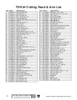
T31635 Motor & Blade List

Summary of Contents for T31634

Page 1: ...N OF THIS MANUAL MAY BE REPRODUCED IN ANY SHAPE OR FORM WITHOUT THE WRITTEN APPROVAL OF GRIZZLY INDUSTRIAL INC CS20597 PRINTED IN CHINA V1 11 19 MODEL T31634 T31635 10 12 DOUBLE BEVEL COMPOUND SLIDING...

Page 2: ...g grinding tool integrity and the usage of personal protective equipment The manufacturer will not be held liable for injury or property damage from negligence improper training machine modifications...

Page 3: ...p 28 Using Table Extensions 29 Using Fence Extensions 29 Cutting Miters 30 Cutting Bevels 31 Compound Cuts 32 Adjusting Depth 33 Cutting Dadoes 34 SECTION 5 SHOP MADE ACCESSORIES 35 Zero Clearance Ins...

Page 4: ...e made every effort to be exact with the instruc tions specifications drawings and photographs in this manual Sometimes we make mistakes but our policy of continuous improvement also means that someti...

Page 5: ...freehand e Never reach around or in back of saw blade f Turn off tool and wait for saw blade to stop before moving workpiece or changing settings g Disconnect power or unplug tool as applicable befor...

Page 6: ...extension at desired length Workpiece Stop Raises to quickly position stock when cutting multiple pieces of equal length Figure 2 Table and fence components Trigger Switch Starts saw Release Button M...

Page 7: ...Release Pin Miter Lock Handle Figure 5 General saw controls Hold Down Clamp Secures workpiece against table Depth Stop Adjusts to allow for shallow cuts such as slots or dadoes Dust Bag Collects wood...

Page 8: ...Cut A cut made with the cutting arm and saw head rotated to an angle between 0 60 from the fence to cut a workpiece at an angle Refer to Page 30 for more details Kickback Miter saw kickback refers to...

Page 9: ...ement 110V Single Phase 60 Hz Full Load Current Rating 15A Minimum Circuit Size 20A Connection Type Cord Plug Power Cord Included Yes Power Cord Length 8 1 2 ft Power Cord Gauge 14 AWG Plug Included Y...

Page 10: ...4 in Fence Max Extended Length 34 in Fence Width 3 8 in Fence Height 2 13 16 in Other Related Info Number of Dust Ports 1 Dust Port Size 1 1 2 in Other Specifications Country of Origin China Warranty...

Page 11: ...se 60 Hz Full Load Current Rating 15A Minimum Circuit Size 20A Connection Type Cord Plug Power Cord Included Yes Power Cord Length 8 1 2 in Power Cord Gauge 14 AWG Plug Included Yes Included Plug Type...

Page 12: ...ase 60 Hz Full Load Current Rating 15A Minimum Circuit Size 20A Connection Type Cord Plug Power Cord Included Yes Power Cord Length 8 1 2 in Power Cord Gauge 14 AWG Plug Included Yes Included Plug Typ...

Page 13: ...kid proof DANGEROUS ENVIRONMENTS Do not use machinery in areas that are wet cluttered or have poor lighting Operating machinery in these areas greatly increases the risk of accidents and injury MENTA...

Page 14: ...ith moving parts or flying debris Make sure they are properly installed undamaged and working correctly BEFORE operating machine FORCING MACHINERY Do not force machine It will do the job safer and bet...

Page 15: ...tation or death can occur from contact with rotating saw blade during operation Workpieces broken blades or flying particles thrown by blade can blind or strike operators or bystanders with deadly for...

Page 16: ...uit To reduce the risk of these hazards avoid over loading the machine during operation and make sure it is connected to a power supply circuit that meets the specified circuit requirements For your o...

Page 17: ...re the cords are rated for outdoor use Outdoor use cords are marked with a W A or a W to signify their rat ing Always check to make sure that the extension cords are in good working order and free of...

Page 18: ...ging materials Often these items get lost in packaging materials while unpack ing or they are pre installed at the factory The following items are needed but not included for the setup assembly of thi...

Page 19: ...ls Placement Location Figure 9 T31634 10 Miter Saw minimum working clearances 15 42 34 Electrical Connection 20 15 Figure 10 T31635 12 Miter Saw minimum working clearances 18 23 45 37 Electrical Conne...

Page 20: ...used to secure the machine in place Machine Base Workbench Hex Bolt Flat Washer Flat Washer Lock Washer Hex Nut Figure 11 Through Mount setup Number of Mounting Holes 4 Dia of Mounting Hardware Neede...

Page 21: ...ver hardware Bevel Release Pin Knob Phillips Head Screws If bevel lock handle and bevel release pin have been disengaged and cutting head does not rotate bevel tilt lock nut may have been overtightene...

Page 22: ...apturing the dust with a dust collection system To attach included dust bag to saw 1 Fit 1 dust bag port over machine port as shown in Figure 22 Check to see that red clip is securely closing bag open...

Page 23: ...ood To test run machine 1 Clear all setup tools away from machine 2 Connect machine to power supply The Test Run consists of verifying the following 1 The motor powers up and runs correctly and 2 the...

Page 24: ...guide To learn more about specific operations read this entire manual seek additional training from experienced machine operators and do additional research outside of this manual by reading how to bo...

Page 25: ...not have large loose knots or plan ahead to avoid cutting through them Wet or Green Stock Cutting wood with a moisture content over 20 causes unneces sary wear on the blades increases the risk of kick...

Page 26: ...ge gullets for large chip removal Flat Top Blade Combination Blade Features Designed to cut both with and across grain 40 50 teeth Alternate top bevel and flat or alternate top bevel and raker tooth p...

Page 27: ...installing it 3 Pull back lower blade guard as pictured in Figure 31 to reveal cover plate screw Figure 31 Cover plate screw location Cover Plate Screw Lower Blade Guard 4 Loosen screw enough to allo...

Page 28: ...of using simple chop cuts for smaller workpieces or push cuts for larger stock Note When cutting workpiece longer than the table support workpiece so it lays flat on the table If you must cut a slight...

Page 29: ...see Figure 36 7 Pull cutting head all the way forward then down beginning cut at leading edge of workpiece slowly pushing back towards fence to complete cut see Figure 39 Table Fence Workpiece 1 Cutt...

Page 30: ...ng Cutting Head Your miter saw is equipped with an operating handle for cutting head control and two additional handles to easily transport your saw For maximum safety during transport or storage lock...

Page 31: ...ce the side or tallest part of the workpiece down flat against the table for maximum support and not on its end where it could flip during a cut see Figure 44 Using Table Extensions The table extensio...

Page 32: ...le position see Figure 48 Figure 48 Cutting arm Miter Release Button Miter Lock Handle 3 Press and hold miter release button see Figure 48 and use miter lock handle to rotate cutting arm to desired an...

Page 33: ...miter or the bevel but one may require the workpiece to be less supported on a thinner edge so users should bear this in mind when selecting which to use To perform a bevel cut 1 DISCONNECT MACHINE FR...

Page 34: ...craftsman also needs to plan for kerf of the blade and whether the left or right side of the blade will make up the finished piece For instance for both inside corners in the chart the left side will...

Page 35: ...of cut 1 DISCONNECT MACHINE FROM POWER 2 Raise cutting head all the way up 3 Loosen depth stop plate screw see Figure 59 and slide plate forward until stop screw will not pass through plate hole when...

Page 36: ...nal cuts see Figure 62 in cen ter of dado to clear out necessary material Dado is complete when channel is complete ly cleared out Cutting Dadoes Commonly used in furniture joinery a dado is a straigh...

Page 37: ...DISCONNECT MACHINE FROM POWER 5 Place straightedge across insert and check to make sure insert is flush with table at front and back of throat If insert is flush with table no adjustments are necessa...

Page 38: ...see Figure 66 Figure 66 Zero clearance fence clamped to existing fence 10 Connect saw to power and cut kerf opening with saw using standard push cut 4 Set miter angle to zero as described on Page 18 5...

Page 39: ...w Stand This stand has a universal design making it com patible with all brands of miter saws It folds for easy storage and is easily set up The stand can support up to 10 feet of material and 500 pou...

Page 40: ...asic Eye Protection T20501 Face Shield Crown Protector 4 T20502 Face Shield Crown Protector 7 T20503 Face Shield Window T20451 Kirova Clear Safety Glasses T20452 Kirova Anti Reflective S Glasses T2045...

Page 41: ...ide table insert channel Re install before operating Monthly Check Vacuum or blow out motor air vents Schedule Cleaning Protecting Cleaning the Model T31634 T31635 is relatively easy Vacuum excess woo...

Page 42: ...eeded Miter Table Path Clean and apply a drop or two of machine oil between table and table seat see Figure 77 as needed Adjust miter to various angles to distribute evenly Figure 77 Miter table path...

Page 43: ...suitable for machine 2 Dull blade 3 Excessive cutting speed pressure 4 Blade installed backwards 5 Improper blade for cut type 6 Workpiece binding pinching against blade 7 Motor brushes at fault 8 Mo...

Page 44: ...ead to perform cut 3 Use correct cutting practices Page 26 4 Install a zero clearance fence or table insert Page 35 to completely eliminate tearout Saw jerks 1 Blade warped damaged dull 2 Workpiece is...

Page 45: ...ead down and lock 4 Lay a framing square flat on miter table pressed against fence and flat part of blade not teeth see Figure 80 6 Adjust fence until it is square with blade then secure setting by ti...

Page 46: ...out of alignment follow these steps to check and adjust its accuracy Squaring Blade To Table Bevel To check bevel angle for squareness to table 1 DISCONNECT MACHINE FROM POWER 2 Set bevel angle to zer...

Page 47: ...screws to lower them Repeat Steps 2 3 until inserts are perfectly flush with surface of table Your miter saw was calibrated at the factory so it shouldn t require any further adjustment However in the...

Page 48: ...rt number PT31634163 for T31634 or PT31635163 for T31635 at the same time when the motor no lon ger reaches full power or when the brushes mea sure less than 1 4 long new brushes are 5 8 long Tools Ne...

Page 49: ...current at the time of printing but may not match your machine If you find this to be the case use the wiring diagram inside the motor junction box CAPACITORS INVERTERS Some capacitors and power inve...

Page 50: ...EAD ELECTRICAL SAFETY ON PAGE 47 110 VAC 1 15 Plug NEUTRAL HOT DKLD WD01 1 LIGHT SWITCH R9 L LED LAMP LASER SWITCH Motor POWER SWITCH CIRCUIT BOARD Operating Handle Top Bottom KCD 117 KCD 117 NC NO C...

Page 51: ...fd Since 8 19 49 READ ELECTRICAL SAFETY ON PAGE 47 Electrical Component Photos Figure 88 Power switch Figure 91 LED lamp Figure 89 Laser Figure 90 Circuit board laser switch and light switch Figure 87...

Page 52: ...34020 PHLP HD SCR M5 8 X 12 4 PT31634004 HOLLOW HANDLE 15 X 54 4 21 PT31634021 FENCE EXTENSION L 5 PT31634005 HEX STANDOFF STUD M6 1 X 28 22 PT31634022 HOLLOW HANDLE 15 X 32 4 6 PT31634006 FOOT 23 PT3...

Page 53: ...51 90 201 220 52 91 202 53 92 203 222 16 54 93 204 55 94 205 56 95 206 57 96 207 20 58 97 208 59 98 60 99 61 100 62 101 63 102 64 103 65 104 66 105 67 106 68 107 69 108 70 109 71 110 72 111 73 104 103...

Page 54: ...4049 SET SCREW M5 8 X 8 107 PT31634107 COMPRESSION SPRING 0 8 X 9 X 18 50 PT31634050 STOP PLATE 108 PT31634108 CUTTING HEAD PIVOT SUPPORT 51 PT31634051 COMPRESSION SPRING 0 8 X 6 X 20 109 PT31634109 C...

Page 55: ...6 216 167 216 168 112 169 113 170 114 171 115 172 59 116 173 117 174 118 175 119 176 120 177 64 121 178 122 179 123 180 214 181 68 125 182 126 183 127 184 128 185 129 186 130 187 131 188 75 132 189 76...

Page 56: ...20 PT31634120 PLATE 177 PT31634177 BUTTON PRESS POST 121 PT31634121 FLAT HD CAP SCR M4 7 X 10 178 PT31634178 TAP SCREW M2 9 X 10 122 PT31634122 FLAT HD CAP SCR M6 1 X 16 179 PT31634179 COMPRESSION SPR...

Page 57: ...EX STANDOFF STUD M6 1 X 28 22 PT31635022 HOLLOW HANDLE 15 X 32 4 6 PT31635006 FOOT 23 PT31635023 HEX STANDOFF STUD M6 1 X 14 7 PT31635007 BASE 24 PT31635024 SET SCREW M6 1 X 14 8 PT31635008 HEX STANDO...

Page 58: ...8 107 35 72 106 51 73 108 38 109 39 86 110 211 87 111 45 46 199 47 201 41 202 42 203 44 204 49 200 74 205 52 207 50 208 56 226 57 88 151 53 89 100 34 212 121 206 90 219 59 91 220 58 92 71 60 93 54 61...

Page 59: ...6 LOBE D26 49 PT31635049 SET SCREW M5 8 X 8 107 PT31635107 COMPRESSION SPRING 0 8 X 9 X 18 50 PT31635050 STOP PLATE 108 PT31635108 CUTTING HEAD PIVOT SUPPORT 51 PT31635051 COMPRESSION SPRING 0 8 X 6 X...

Page 60: ...80 114 134 160 185 81 115 161 186 83 116 135 187 82 117 141 163 188 84 118 139 164 189 85 119 142 166 190 120 143 165 194 121 144 167 192 122 145 168 193 123 146 169 191 216 147 217 195 124 148 171 1...

Page 61: ...121 FLAT HD CAP SCR M4 7 X 10 178 PT31635178 TAP SCREW M2 9 X 10 122 PT31635122 FLAT HD CAP SCR M6 1 X 16 179 PT31635179 COMPRESSION SPRING 1 X 30 X 8 123 PT31635123 DUST CHUTE 180 PT31635180 MICRO SW...

Page 62: ...erating 13 Know what causes kickback and how to prevent it 14 Never remove jammed cutoff workpiece when the blade is moving 15 Plan cuts so workpiece always remains supported 16 Always return carriage...

Page 63: ...for incidental contingent special or consequential damages arising from the use of our products The manufacturers reserve the right to change specifications at any time because they constantly strive...

Page 64: ......

Reviews: