


Model T31634/T31635 (Mfd. Since 8/19)
-45-
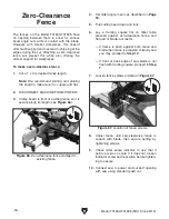
Adjusting
Table Inserts
The table inserts must sit perfectly flush with the
table to provide a smooth, continuous surface for
the workpiece to rest on. The inserts are held in
place by six Phillips head screws (see
Figure 85).
The inserts should be checked and adjusted any
time they are removed and replaced, after pro-
longed use, or any time you notice the workpiece
does not slide smoothly over the inserts.
Tools Needed
Qty
Phillips Head Screwdriver #2 ............................ 1
Straightedge 12" ................................................ 1
To check and adjust insert:
1. DISCONNECT MACHINE FROM POWER!
2. Place straightedge across inserts and check
to make sure inserts are flush with table at
front and back of throat.
— If inserts are flush with table, no adjust-
ments are necessary.
— If inserts are not flush with table, proceed
to
Step 3.
3. One at a time, either loosen screws to raise
inserts, or tighten screws to lower them.
Repeat
Steps 2–3 until inserts are perfectly
flush with surface of table.
Your miter saw was calibrated at the factory so it
shouldn't require any further adjustment. However,
in the case that your saw is knocked out of align-
ment, or you would like to adjust the bevel stop to
a value less than 45
˚, follow the below steps.
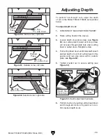
Adjusting
45˚ Bevel Stop
To adjust 45˚ bevel stop:
1. DISCONNECT MACHINE FROM POWER!
2. Make sure 0˚ bevel stop is accurate by fol-
lowing steps in
Squaring Blade to Table on
Page 44.
3. Set miter angle to 0˚ and fully extend fence
extensions.
4. Set bevel angle to 45˚.
5. Measure angle between table and blade (not
teeth).
— If angle is 45
˚, bevel stop is calibrated cor-
rectly, and no adjustment is necessary. If
you wish to adjust bevel stop to an angle
less than 45
˚, proceed to Step 6.
— If angle is not 45
˚, bevel stop needs
adjustment. Proceed to
Step 6.
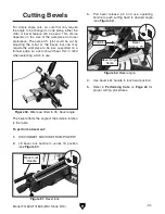
6. Turn left set screw (see Figure 84) until 45˚
(or other desired angle) is achieved.
Tools Needed
Qty
45
˚ Angle Tool ................................................... 1
Hex wrench 3mm .............................................. 1
Figure 85. Table insert screws.
Figure 84. Left set screw location.
Summary of Contents for T31634
Page 64: ......


