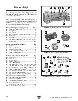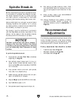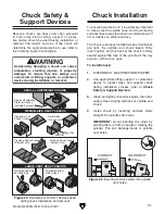
-22-
Model G0949G (Mfd. Since 01/22)
HEAVY LIFT!
Straining or crushing injury
may occur from improperly
lifting machine or some of
its parts. To reduce this risk,
get help from other people
and use a forklift (or other
lifting equipment) rated for
weight of this machine.
Assembly
IMPORTANT: During the following steps, DO
NOT attempt to lift or move this lathe without
using the proper lifting equipment (such as fork-
lift or crane) and the necessary assistance from
other people. Each piece of lifting equipment must
be rated for at least 1000 lbs. to support dynamic
loads that may be applied while lifting.
4. Using a forklift, move crate to machine work
site location.
5. Remove crate top and sides, components
inside crate, and blocks around machine
base.
6. Unbolt lathe from shipping pallet.
7. Thread handles into carriage and cross slide
handwheels, as shown in
Figure 16.
To assemble lathe:
1. Position left and right cabinets approximately
36½" apart in prepared location.
2. Secure panel brackets to cabinets with (4)
M6-1 x 12 cap screws, 6mm lock washers,
and 6mm flat washers (see
Figure 14).
3. Install front panel onto panel brackets with (4)
M6-1 x 12 cap screws, (8) 6mm flat washers,
(4) 6mm lock washers, and (4) M6-1 hex nuts
(see
Figure 15).
The machine must be fully assembled before it
can be operated. Before beginning the assembly
process, refer to
Needed for Setup and gather
all listed items. To ensure the assembly process
goes smoothly, first clean any parts that are cov-
ered or coated in heavy-duty rust preventative (if
applicable).
Figure 16. Handwheels installed.
Cross Slide
Handle
Carriage
Handle
Figure 15. Front panel installed.
Front Panel
Figure 14. Panel brackets installed (rear view).
Brackets
Cabinets
x 4
Summary of Contents for G0949G
Page 108: ......


