-70-
Model G0949G (Mfd. Since 01/22)
1. DISCONNECT MACHINE FROM POWER!
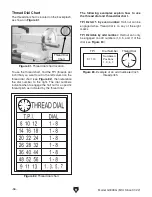
2. Loosen locking set screw (see Figure 105).
Figure 105. Compound rest gib components.
Gib Screw
(1 of 2)
Locking
Set Screw
3. Adjust gib screws as follows:
— To increase slide tension, loosen rear gib
screw
1
⁄
8
turn, and tighten front gib screw
1
⁄
8
turn.
— To decrease slide tension, loosen front gib
screw
1
⁄
8
turn, and tighten rear gib screw
1
⁄
8
turn.
4. After each adjustment, use compound rest
handwheel to test compound rest movement.
5. Repeat Steps 3–4 until compound rest move-
ment is acceptable.
Saddle Gib
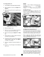
The saddle gib is located on the bottom of the
back edge of the cross slide (see
Figure 106).
This gib is designed differently than the cross or
compound slide gibs. Instead of being a wedge-
shaped plate, it is a flat bar. The gib pressure is
applied by four set screws. Jam nuts secure these
set screws in place, so they will not loosen during
operation.
Tools Needed
Qty
Open-End Wrenches 7, 10mm ....................1 Ea.
To adjust saddle gib:
1. DISCONNECT MACHINE FROM POWER!
2. Clean and lubricate lathe bedways (refer to
Page 62).
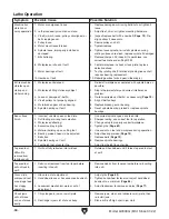
3. If carriage lock (see Figure 107) is tight,
loosen it
two turns.
4. To access saddle gib, remove backsplash.
5. Loosen the hex nuts on four set screws
shown in
Figure 106, and adjust set screws
same amount as follows:
— To tighten carriage gib, tighten set screw
in equal amounts.
— To loosen gib, loosen set screws in equal
amounts.
Figure 106. Saddle gib components.
Gib
Set Screws & Jam Nuts
Carriage
Lock
Figure 107. Location of carriage lock.
Compound Rest Gib
The compound rest gib is located on the bottom of
the back edge of the compound rest (see
Figure
105). This gib is a wedge-shaped plate. The gib
pressure is applied by two set screws.
When adjusting the compound rest be aware
directions to increase or decrease the tension are
reversed from cross slide gib.
Summary of Contents for G0949G
Page 108: ......

