Model G0949G (Mfd. Since 01/22)
-51-
To set power feed rate of 0.0075 in./rev:
1. Locate cell on feed rate chart that lists 0.0075
in./rev., as shown in
Figure 66.
Figure 66. Feed rate levers positioned for
0.0075 in./rev.
Feed Rate
Selector
Feed
Direction
Selector
Feed/
Thread
Selector
2. Locate the applicable positions for feed direc-
tion selector, feed rate selector, and feed/
thread selector.
3. Locate end gear configuration callout, and
position end gears in correct configuration,
as shown on feed rate chart. For this configu-
ration install a 45T gear in Z1 position and
mesh it with a 70T gear at Z4 position. Install
a 75T gear in Z2 position and mesh it with
25T gear at Z3 position.
Note: The L gear is always 90T in power feed
configuration.
4. Move selector levers to correct positions:
feed direction selector to left, feed rate selec-
tor to position "A", and feed/thread selector to
right (feed setting), as shown in
Figure 66.
5. Move leadscrew feed rod selection lever up.
The carriage is now set up for a power feed
rate of 0.0075 in./rev.
The following subsections explain how to configure
the end gears. The gears must be configured
according to the feed and threading charts in
order to perform specific power feed and threading
operations (see
Figure 67).
To set the gears up properly, according to the
particular gears and positions shown in the charts,
you need a basic understanding of gear positioning
on the lathe and how this is represented in
the chart illustrations. In
Figure 67, identify the
following:
—40T gear
—Z1 & Z2 (outer & inner) combination gear
—Z3 & Z4 (inner & outer) combination gear
—L gear
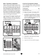
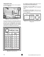
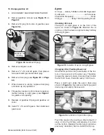
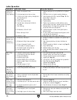
End Gears
The following subsections explain how to con-
figure the end gears, which are accessed by
removing the end-gear cover on the side of the
headstock.
Gear selection depends upon which feed speed
is selected (see
Figure 68). To complete a power
feed configuration, install a 75T or 80T gear in Z2
position, a 45T gear in Z1 position, a 20T, 25T, or
30T gear in Z3 position, and a 70T or 80T gear in
Z4 position. Install a 90T gear in L position. Mesh
gears together and secure in place (see
Figures
69
–70).
Note: The L gear is always a 90T in power feed
configuration.
Power Feed Configuration
Figure 67. End gear identification.
L Gear
40T Gear
Z3
(Inner)
Z2
(Inner)
Z4
(Outer)
Z1
(Outer)
Summary of Contents for G0949G
Page 108: ......


