background image

-44-

Model G0949G (Mfd. Since 01/22)

The  carriage,  cross  slide,  and  compound  rest 
have locks that can be tightened to provide addi-
tional  rigidity  during  operation,  especially  during 
heavy- cuts.

See

 Figures 5253 to identify the locks for each 

device.

Tool Needed 

Qty

Hex Wrench 6mm .............................................. 1

Follow Rest

Carriage & Slide 

Locks

Tools Needed  

Qty

Hex Wrench 5mm .............................................. 1
Open-End Wrench 14mm .................................. 1

Tip: To reduce the effects of friction, lubricate the 
finger tips with generous amounts of anti-sieze 
lubricant during operation.

The follow rest mounts to the saddle with two cap 
screws  (see 

Figure  51).  It  is  used  on  long  slen-

der  parts  to  prevent  workpiece  deflection  from 
the pressure of the cutting tool during operation. 
Adjust  the  finger  adjustment  knobs  in  the  same 
manner as those on the steady rest.

Figure 51

.

 Follow rest components.

Finger 

Lock 

Nut

Cap 

Screws

Finger 

Adjustment 

Knob

Finger

Figure 52. Location of carriage and cross slide 

locks.

Cross Slide

Lock

Carriage

Lock

Figure 53. Location of compound rest lock.

Compound 

Rest Lock

Summary of Contents for G0949G

Page 1: ... models manufactured since 01 22 Keep for Future Reference COPYRIGHT DECEMBER 2021 BY GRIZZLY INDUSTRIAL INC WARNING NO PORTION OF THIS MANUAL MAY BE REPRODUCED IN ANY SHAPE OR FORM WITHOUT THE WRITTEN APPROVAL OF GRIZZLY INDUSTRIAL INC JM22163 PRINTED IN CHINA V1 12 21 ...

Page 2: ...ng grinding tool integrity and the usage of personal protective equipment The manufacturer will not be held liable for injury or property damage from negligence improper training machine modifications or misuse Some dust created by power sanding sawing grinding drilling and other construction activities contains chemicals known to the State of California to cause cancer birth defects or other repr...

Page 3: ...ck 37 Centers 40 Steady Rest 43 Follow Rest 44 Carriage Slide Locks 44 Compound Rest 45 Tool Post 45 Spindle Spider 47 Manual Feed 47 Spindle Speed 48 Power Feed 49 End Gears 51 Threading 54 SECTION 5 ACCESSORIES 57 SECTION 6 MAINTENANCE 58 Schedule 58 Cleaning Protecting 58 Lubrication 59 Machine Storage 64 SECTION 7 SERVICE 65 Troubleshooting 65 Backlash Adjustment 68 Gib Adjustment 69 Half Nut ...

Page 4: ...lp Before calling make sure you write down the manufacture date and serial number from the machine ID label see below This information is required for us to provide proper tech support and it helps us determine if updated documentation is available for your machine Manufacture Date Serial Number Manual Accuracy We stand behind our machines If you have ques tions or need help contact us with the in...

Page 5: ...stand the instructions in this manual J Storage Cabinet K Stand Mounting Points L Carriage M 3 Drawer Cabinet N Quick Change Gearbox Levers O Spindle Speed Range Lever P Spindle Speed Dial Q Spindle Speed Digital Readout R Change Gear and Belt Safety Cover A Headstock B Master Power Switch C 3 Jaw Chuck 6 D Steady Rest E Quick Change Tool Post F Compound Rest G Tailstock H Leadscrew I Feed Rod B C...

Page 6: ...i tion for counterclockwise rotation forward Move switch to REV position for clockwise rotation reverse Move switch to 0 position to stop spindle rotation F STOP Button Stops spindle rotation G Quick Change Gearbox Levers Controls leadscrew and feed rod speeds for threading and feeding operations H E Stop Button Stops all machine functions Twist clockwise to reset I Thread and Feed Charts Display ...

Page 7: ... Secures carriage in place for greater rigidity M Thread Dial Indicates when to engage the half nut during inch threading operations N Half Nut Lever Engages disengages half nut for threading operations O Feed Selection Lever Selects power feed for carriage or cross slide P Carriage Handwheel Moves carriage along bed Dial is graduated in increments of 0 01 1 2 per full revolution Q Cross Slide Han...

Page 8: ...wheel Moves quill toward or away from spindle End Gears Configuring the end gears shown in Figure 6 controls the speed of the leadscrew for thread ing operations or the feed rod for power feed operations Figure 6 End gear components End Gears Tailstock Figure 4 Tailstock controls W V R S T V U Figure 5 Additional tailstock controls X W Tailstock Offset Screw Offsets tailstock left or right from sp...

Page 9: ... The movement of a cutting tool into a workpiece Fixture A device that securely holds the workpiece in place during cutting operation as opposed to a jig which is used to hold and guide a workpiece through an operation Gib A tapered wedge located along a sliding member to take up wear or to ensure a proper fit Headstock The major lathe component that houses the spindle and motor drive system to tu...

Page 10: ... 53 in Footprint Length x Width 58 1 2 x 15 in Shipping Dimensions Carton 1 Type Wood Crate Content Machine Weight 717 lbs Length x Width x Height 65 x 30 x 30 in Must Ship Upright Yes Carton 2 Type Wood Pallet Content Stand Weight 133 lbs Length x Width x Height 32 x 24 x 20 in Must Ship Upright Yes Electrical Power Requirement 110V Single Phase 60 Hz Full Load Current Rating 15A Minimum Circuit ...

Page 11: ...ength with 4 Jaw Chuck 19 13 16 in Spindle Length with Faceplate 15 13 16 in Tailstock Info Tailstock Quill Travel 3 1 8 in Tailstock Taper MT 3 Tailstock Barrel Diameter 1 261 in Threading Info Number of Longitudinal Feeds 12 Range of Longitudinal Feeds 0 0025 0 012 in rev Number of Cross Feeds 10 Range of Cross Feeds 0 0015 0 0056 in rev Number of Inch Threads 21 Range of Inch Threads 8 56 TPI N...

Page 12: ... 6 75 oz Apron Fluid Type ISO 68 eg Grizzly T23962 Mobil Vactra 2 Other Specifications Country of Origin China Warranty 1 Year Approximate Assembly Setup Time 1 Hour Serial Number Location Machine ID Label ISO 9001 Factory Yes Features Digital Spindle Speed Readout Outboard Spindle Support Spider with 4 Brass Tipped Bolts D1 4 Camlock Spindle Full Length Splash Guard 200 Series Quick Change Tool P...

Page 13: ...id proof DANGEROUS ENVIRONMENTS Do not use machinery in areas that are wet cluttered or have poor lighting Operating machinery in these areas greatly increases the risk of accidents and injury MENTAL ALERTNESS REQUIRED Full mental alertness is required for safe operation of machin ery Never operate under the influence of drugs or alcohol when tired or when distracted For Your Own Safety Read Instr...

Page 14: ...h moving parts or flying debris Make sure they are properly installed undamaged and working correctly BEFORE operating machine FORCING MACHINERY Do not force machine It will do the job safer and better at the rate for which it was designed NEVER STAND ON MACHINE Serious injury may occur if machine is tipped or if the cutting tool is unintentionally contacted STABLE MACHINE Unexpected movement dur ...

Page 15: ...dle with deadly force Make sure workpiece is properly secured before starting the lathe CHUCKS Chucks can be heavy and difficult to hold During installation and removal protect your hands and precision bed ways by using a chuck cradle or piece of plywood over the bed ways Use lifting equipment as necessary for large chucks STOPPING SPINDLE Always allow spindle to completely stop on its own or use ...

Page 16: ...late or a larger chuck if pos sible Otherwise the workpiece could be thrown from the lathe during operation resulting in serious impact injury or death CLAMPING FORCE Inadequate clamping force can lead to the workpiece being thrown from the chuck and striking the operator or bystanders Maximum clamping force is achieved when the chuck is properly maintained and lubricated all jaws are fully engage...

Page 17: ...t To reduce the risk of these hazards avoid over loading the machine during operation and make sure it is connected to a power supply circuit that meets the specified circuit requirements For your own safety and protection of property consult an electrician if you are unsure about wiring practices or electrical codes in your area Note Circuit requirements in this manual apply to a dedicated circui...

Page 18: ...cord size gets longer and the gauge size gets smaller higher gauge numbers indicate smaller sizes Any extension cord used with this machine must be in good condition and contain a ground wire and matching plug receptacle Additionally it must meet the following size requirements Minimum Gauge Size 12 AWG Maximum Length Shorter is Better 50 ft Grounding Plug Requirements Figure 7 Typical 5 15 plug a...

Page 19: ...onnection A power source that meets the minimum cir cuit requirements for this machine review Power Supply on for details For Assembly Shop rags Cleaner degreaser Page 20 Quality metal protectant lubricant Safety glasses for each person Floor mounting hardware Page 24 Brass hammer Silicon caulk as needed Caulking gun Preparation 1 Unpack the lathe and inventory the contents of the box crate 2 Clea...

Page 20: ...se Components Figure 9 Qty H Toolbox 1 I Faceplate 93 8 1 J Handwheel Handles 2 K 4 Jaw Independent Chuck 6 1 L 4 Jaw Chuck Wrench 1 Toolbox Components Figure 10 Qty M Oil Bottle 1 N Chuck Key 1 O Spindle Wrench 1 P Arbor B16 x MT 3 1 Q End Gears 25T 30T 40T 45T 50T 55T 63T 65T 70T 75T 80T 2 90T 60T 1 Ea R Tapered Spindle Sleeve MT 5 x MT 3 1 S 3 Jaw Chuck Outside Jaws 3 T Hex Wrenches 2 2 5 3 4 5...

Page 21: ...e unpack ing or they are pre installed at the factory Figure 11 Cabinet inventory components Cabinet Components Figure 11 Qty AC Left Cabinet 1 AD Front Panel 1 AE Right Cabinet 1 AF Panel Brackets 2 AG Chip Pan 1 AH Cabinet Fasteners not shown Hex Bolts M10 1 5 x 35 6 Flat Washers 10mm 12 Hex Nuts M10 1 5 6 Cap Screws M6 1 x 12 8 Lock Washers 6mm 8 Flat Washers 6mm 18 Hex Nuts M6 1 4 AC AD AE AF ...

Page 22: ...ing gather the following Disposable rags Cleaner degreaser WD 40 works well Safety glasses disposable gloves Plastic paint scraper optional Basic steps for removing rust preventative 1 Put on safety glasses 2 Coat the rust preventative with a liberal amount of cleaner degreaser then let it soak for 5 10 minutes 3 Wipe off the surfaces If your cleaner degreas er is effective the rust preventative w...

Page 23: ...t for safe operation and lon gevity of machine components For best results operate this machine in a dry environment that is free from excessive moisture hazardous chemi cals airborne abrasives or extreme conditions Extreme conditions for this type of machinery are generally those where the ambient temperature range exceeds 41 104 F the relative humidity range exceeds 20 95 non condensing or the e...

Page 24: ... Unbolt lathe from shipping pallet 7 Thread handles into carriage and cross slide handwheels as shown in Figure 16 To assemble lathe 1 Position left and right cabinets approximately 36 apart in prepared location 2 Secure panel brackets to cabinets with 4 M6 1 x 12 cap screws 6mm lock washers and 6mm flat washers see Figure 14 3 Install front panel onto panel brackets with 4 M6 1 x 12 cap screws 8 ...

Page 25: ... move tailstock and carriage to right end of bedway then lock them in place Note Before attempting to move carriage make sure carriage lock is loose half nut is disengaged and feed selection lever is dis engaged Refer to Page 5 to identify these controls 9 Wrap two lifting straps see Figure 17 around bedway pedestals and route behind feed rod and leadscrew Then attach them to safety hook or forks ...

Page 26: ...e Machine Base Concrete Lag Screw Lag Shield Anchor Flat Washer Drilled Hole Figure 19 Popular method for anchoring machinery to a concrete floor Anchoring to Concrete Floors Leveling Leveling machinery helps precision components such as bedways remain straight and flat during the lifespan of the machine Components on a machine that is not level may slowly twist due to the dynamic loads placed on ...

Page 27: ...running lathe without oil in reservoirs will not be covered under warranty Refer to Lubrication section beginning on Page 59 for checking and adding oil In addition to reservoirs we also recommend that you lubricate all other points on machine at this time To do this follow steps provided in mainte nance schedule on Page 58 Note If this lathe was shipped with oil in the res ervoirs do not change t...

Page 28: ...achine Half Nut Lever Half Nut Lever Engaged Half Nut Lever Disengaged Cross Slide Disengaged Feed Selection Lever Carriage Figure 22 Disengaging carriage components Feed Selection Lever Note In the next step you may need to rock the chuck back and forth as you make the adjust ments so that the gears will mesh together 7 To ensure carriage components do not unex pectedly move during the following ...

Page 29: ... further Always disconnect the machine from power when investigating or correcting potential problems 14 Press E Stop button to turn machine OFF 15 WITHOUT resetting E Stop button try to start machine by pressing START button The machine should not start If spindle rotation does not start E Stop safety feature is working correctly If spindle rotation does start immediately turn machine OFF and dis...

Page 30: ...ze the life of spindle bearings and other precision components by thoroughly lubricating them before placing them under load After spindle break in is complete we recommend changing headstock and gearbox oil to remove any metal particles or debris that are present from the assembly and break in process The break in must be performed in succession with the Test Run procedure described in this manua...

Page 31: ...ve tooling into workpiece for operation 13 When finished cutting presses STOP button waits for the spindle rotation to stop and then removes the workpiece The purpose of this overview is to provide the nov ice machine operator with a basic understanding of how the machine is used during operation so the machine controls components discussed later in this manual are easier to understand Due to the ...

Page 32: ...urning between centers off center turning and boring Never use spindle speeds faster than chuck RPM rating or safe limits of your workpiece Excessive spindle speeds greatly increase risk of workpiece or chuck being thrown from machine with deadly force Camlock Stud Installation To install camlock studs 1 Lightly oil threads of each stud 2 Thread studs until datum line is flush with or just above s...

Page 33: ...les of common devices used during chuck installation and removal Chuck Installation To ensure accurate work it is extremely important to make sure the spindle nose and chuck mating surfaces tapers are clean Even a small amount of lint or debris can affect accuracy The chuck is properly installed when all camlocks are tight the spindle and chuck tapers firmly lock together and the back of the chuck...

Page 34: ...istration Marks Registration Marks Lightly stamp registration marks across the mating seams of chuck components These marks will help you re install the chuck in the same position after removal which ensures consistent chuck balance and turning results and allows the same camlocks and studs to operate together for consistent locking and unlocking 7 Verify that chuck fits spindle properly by checki...

Page 35: ...y throw the workpiece Instead use an independent jaw chuck or a faceplate Scroll Chuck Clamping Insufficient Jaw Clamping Unstable Workpiece Bar Stock Cylinder Unsafe Jaw Position Poor Scroll Gear Engagement Safer Inside Jaw Use Unsafe Inside Jaw Use Unsafe Jaw Position Safer Outside Jaw Use Poor Scroll Gear Engagement Unsafe Jaw Position and Poor Scroll Gear Engagement Poor Grip Unstable Workpiec...

Page 36: ...t of NLGI 2 grease to surfaces of removed jaw set Store in safe place free from moisture and abrasives 6 Rotate chuck key clockwise until you see tip of outer scroll gear lead thread about to enter a jaw guide see below Lead Thread 1 Figure 34 Lead thread on scroll gear 7 Insert jaw 1 into jaw guide and hold jaw against scroll gear 8 Rotate chuck key clockwise one turn to engage tip of scroll gear...

Page 37: ...vice to protect ways refer to Chuck Safety Support Devices section for more details 3 Use chuck key to open each jaw so work piece will fit into spindle opening and lay flat against chuck face and jaw steps 4 With help from another person or a holding device position workpiece so it is centered in chuck Figure 35 4 jaw chuck tightening sequence 1 2 3 4 Workpiece Center Point Figure 36 Example of a...

Page 38: ...piece to be thrown from lathe with deadly force To reduce this risk use a minimum of THREE independent clamping devices to hold workpiece onto faceplate To mount a non concentric workpiece to a faceplate 1 DISCONNECT MACHINE FROM POWER 2 Position appropriate device across bed ways to protect them from any potential damage from workpiece contact during installation 3 With help from another person o...

Page 39: ...enter for tapered turning The tailstock quill also features independent adjustment controls that allow it to be advanced toward the spindle or locked firmly in position Figure 38 Tailstock controls and features Quill Quill Lock Lever Quill Handwheel Offset Adjustment Screw 1 of 2 Tailstock Lock Lever Graduated Dial Increments 0 001 One Full Revolution 0 100 Increments on Quill Inch 0 3 in 1 8 Incr...

Page 40: ...l Check to see if it is firmly seated by attempting to twist it a firmly seated tool will not twist 4 Unlock tailstock and move it until tip of tool is close to but not touching workpiece then lock tailstock 5 Start spindle rotation unlock quill lock lever then turn quill handwheel clockwise to feed tool into workpiece Removing Tooling 1 Use shop rag to hold tool 2 Rotate quill handwheel countercl...

Page 41: ...terline when it is supposed to be turning results will be inaccurate along the length of the workpiece Items Needed Qty Hex Wrench 6mm 1 Round Stock 2 x 6 2 Precision Level 1 Figure 41 Turning a dead center To align tailstock to spindle centerline 1 Use precision level to make sure bedway is level from side to side and from front to back If bedway is not level correct this condition before continu...

Page 42: ... of lathe 1 2 the dis tance of taper amount as shown below Move tailstock toward front of lathe 1 2 the amount of taper Looking down from above Figure 43 Adjust tailstock toward the operator If test stock is thinner at tailstock end move tailstock toward back of lathe 1 2 the distance of taper amount as shown below Looking down from above Move tailstock toward back of lathe 1 2 the amount of taper...

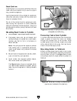
Page 43: ...operational pressures which could make it very difficult to remove the center 3 Mount chuck or faceplate onto spindle which ever is correct for your operation 4 Insert center into tapered spindle sleeve then insert center into spindle bore The Figure below shows an example photo of a dead center installed in spindle using a lathe dog and faceplate for turning between centers Mounting Dead Center i...

Page 44: ...overtightening cen ter against workpiece or it may become difficult to remove later and it will result in excessive friction and heat which may dam age workpiece and center 1 DISCONNECT MACHINE FROM POWER 2 Drill center holes in both ends of workpiece 3 Install dead center in spindle with lathe dog and chuck faceplate or drive plate then install live center or carbide tipped dead cen ter in tailst...

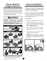
Page 45: ...ghten hex nut shown in Figure 49 to secure it in place 4 Loosen finger lock nuts see Figure 49 so position of fingers can be adjusted Figure 50 Example of workpiece mounted in steady rest Finger Adjustment Knob 1 of 3 6 Tighten finger lock nuts to secure settings Note To reduce the effects of friction lubri cate the fingers with anti sieze lubricant such as Grizzly Model T23962 ISO Moly D Way Oil ...

Page 46: ...tion lubricate the finger tips with generous amounts of anti sieze lubricant during operation The follow rest mounts to the saddle with two cap screws see Figure 51 It is used on long slen der parts to prevent workpiece deflection from the pressure of the cutting tool during operation Adjust the finger adjustment knobs in the same manner as those on the steady rest Figure 51 Follow rest components...

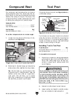
Page 47: ...f tool mounted in tool post Cutting Tool Tool Post Set Screw Tool Holder Thumb Wheel Top Nut Lock Lever Tool holders can be quickly loaded and unloaded using the lock lever and rotated by loosening the top nut Tools up to 5 8 can be secured by tighten ing the tool holder set screws The thumb wheel rotates to adjust cutting tool height To install tool in tool post 1 Position tool in holder so cutti...

Page 48: ...ock must be aligned to the spindle centerline refer to Aligning Tailstock To Spindle Centerline for detailed instructions For most operations the cutting tool tip should be aligned with the spindle centerline as illustrated below Figure 56 Cutting tool aligned with spindle centerline viewed from tailstock Cutting Tool Spindle Center Line To align cutting tool with tailstock center 1 Mount cutting ...

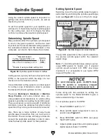
Page 49: ...carriage 1 2 Carriage Handwheel The cross slide handwheel moves the tool to ward and away from the work Adjust the position of the graduated scale by loosening the thumb knob holding the handwheel with one hand and turning the dial with the other then tightening the thumb knob The cross slide handwheel has a direct read graduated dial which shows the total amount of material removed from the diame...

Page 50: ...a wealth of additional information about the variables that affect cutting speed and they are a good educational resource Also there are a large number of easy to use spindle speed calculators that can be found on the internet These sources will help you take into account the applicable variables in order to deter mine the best spindle speed for the operation Selecting one of the two spindle speed...

Page 51: ...ough there is a lock out device to prevent this it could break if forced Power Feed Controls Use Figures 62 66 and the following descrip tions to understand the power feed controls Note Before using power feed you may have to reconfigure the end gears depending on how they are set up Refer to End Gears on Page 51 for detailed instructions Figure 62 Power feed controls on the headstock C To avoid d...

Page 52: ...tions to achieve desired result see Figure 63 Figure 63 Feed rate chart D Figure 64 Apron power feed controls E The feed rate chart displays settings for head stock feed controls for feed rates Using the controls on the lathe follow along with the example below to better understand how to set up the lathe for the desired power feed rate Examining the chart you will see a series of boxes separated ...

Page 53: ...The following subsections explain how to configure the end gears The gears must be configured according to the feed and threading charts in order to perform specific power feed and threading operations see Figure 67 To set the gears up properly according to the particular gears and positions shown in the charts you need a basic understanding of gear positioning on the lathe and how this is represe...

Page 54: ...n the L row shown in the chart below indi cates a spacer is to be installed in that position Inch Threading Configuration Figure 71 Inch TPI threading configuration B A C 8 16 32 9 18 36 10 20 40 11 22 44 12 24 48 13 26 52 14 28 56 90 4540 70 H H H H H H H H H H H H H 80 80 80 80 60 65 60 70 70 70 55 80 40 40 30 40 70 75 75 50 50 55 50 60 Z Z Z Z L H End Gear Configuration Feed Rate Selectors Figu...

Page 55: ...0 80 63 75 40 45 50 80 63 63 63 45 55 30 60 60 50 Z 0 4 0 8 0 5 0 75 1 75 3 5 3 0 1 5 1 25 1 0 2 5 2 0 H End Gear Configuration Feed Rate Selector Figure 74 Metric feed chart end gears Z1 Position Z3 Position Z4 Position L Position Z2 Position End Gear Configuration Example Follow the example below to better understand how to read the gear charts and configure the end gears accordingly Tools Neede...

Page 56: ...Threading Configuration The threading charts on the headstock face see Figure 77 display settings for inch and metric threading The lathe is now set up to cut 22 TPI threads Figure 78 Feed direction and feed thread selector settings for 22 TPI Feed Thread Selector Feed Direction Selector Feed Rate Selector Figure 77 22 TPI threading configuration B A C 8 16 32 9 18 36 10 20 40 11 22 44 12 24 48 13...

Page 57: ... inch threading opera tions Loosen the cap screw on the thread dial see Figure 80 pivot the gear teeth so they mesh with the leadscrew threads then tighten the cap screw Note You must leave the half nut engaged from the beginning until the turning is complete for this type of operation The thread dial is not used for metric threading Thread Dial When threading we recommend using the slowest speed ...

Page 58: ...ead pitch as indicated by the thread dial Thread Dial TPI Dial Number 9 11 13 Numbered Positions 1 3 5 7 1 3 5 7 Figure 83 Example of an odd numbered inch thread pitch The following examples explain how to use the thread dial and thread dial chart TPI Divisible by even number Half nut can be engaged when thread dial is on any of the eight marks TPI Divisible by odd number Half nut can only be enga...

Page 59: ...5 gallon quantities T26419 Syn O Gen Multi Purpose Grease Syn O Gen Multi purpose Synthetic Grease is for mulated with 100 pure synthesized hydrocarbon base stocks to impart its remarkable properties Figure 85 Model T26419 Syn O Gen Grease SBCE3450 How to Run a Lathe Book First printed in 1907 by South Bend Lathe this 56th edition is an exact reprint from 1966 Well illustrated with vintage photos ...

Page 60: ...udes any surface that is vulnerable to rust if left unprotected especially parts that are exposed to water soluble cutting fluid Use a quality ISO 68 way oil see Page 57 for offerings from Grizzly to prevent corrosion Schedule Ongoing To minimize your risk of injury and maintain proper machine operation shut down the machine imme diately if you ever observe any of the items below and fix the probl...

Page 61: ...es the lubricant with the motion of the gears much like an automotive manual transmis sion Change the oil after the first 300 hours of use then every 1000 hours Checking Oil Level The headstock reservoir has the proper amount of oil when the oil level in the sight glass is approxi mately halfway The oil sight glass is located on the on the lower left side of the headstock as shown in Figure 88 Fig...

Page 62: ...te selector near the bottom of the control panel Figure 90 Location of gearbox oil sight glass and drain plug Gearbox Oil Sight Glass Figure 89 Headstock fill and drain plugs 1 DISCONNECT MACHINE FROM POWER 2 Open end gear cover 3 Remove V belts so that oil does not get on them necessitating their replacement refer to Replacing V Belts on Page 72 for detailed instructions 4 Remove fill plug from t...

Page 63: ...at the level is approximately halfway in the sight glass Figure 93 Location of apron oil sight glass Changing Oil Flushing Reservoir Small metal particles may accumulate at the bot tom of the reservoir with normal use Therefore to keep the reservoir clean drain and flush it after the first 300 hours then after every 1000 hours Place a catch pan under the apron drain plug shown in Figure 94 then re...

Page 64: ...lathe is in a moist or dirty environment increase the lubrica tion frequency Ball Oilers Oil Type Grizzly T23963 or ISO 32 Equivalent Oil Amount 1 or 2 Squirts Lubrication Frequency Daily This lathe has 16 ball oilers that should be oiled on a daily basis before beginning operation Refer to Figures 96 99 for their locations Ball Oilers Proper lubrication of ball oilers is done with a pump type oil...

Page 65: ...sible to keep the gears free of dust or debris from the outside environment Figure 100 End gears E Figure 99 Tailstock ball oiler End Gears Grease Type T26419 or NLGI 2 Equivalent Lubrication Every 50 Operating Hours The end gears shown in Figure 100 should always have a thin coat of heavy grease to minimize corrosion noise and wear Wipe away excess grease that could be thrown onto the V belt and ...

Page 66: ...1 Re install V belt and tension it refer to Page 72 if you removed it for storage purposes 2 Remove moisture absorbing desiccant packs from electrical box 3 Repeat Test Run and Spindle Break In pro cedures beginning on Pages 25 28 To prevent the development of rust and corrosion the lathe must be properly prepared if it will be stored for a long period of time Doing this will ensure the lathe rema...

Page 67: ...e 5 Test replace if at fault 6 Ensure circuit is free of shorts Reset circuit breaker or replace fuse 7 Correct motor wiring connections Page 82 8 Fix broken wires or disconnected corroded connections 9 Replace START button 10 Inspect replace if at fault 11 Replace motor Machine stalls or is underpowered 1 Feed rate cutting speed too fast 2 Improper tooling or workpiece material 3 Gearbox at fault...

Page 68: ...4 Align V belt pulleys 5 Replace broken gear or bearing 6 Reset spindle bearing preload or replace spindle bearings Bad surface finish 1 Incorrect spindle speed or feed rate 2 Dull tooling or wrong tool selection 3 Workpiece deflecting 4 Excessive play in gibs 5 Material building up on cutting tool 6 Bearing preload needs to be adjusted 7 Belts bad 8 Spindle bearings at fault 9 Tool height not at ...

Page 69: ... 1 Tool holder not tight enough 2 Cutting tool sticks too far out of tool holder lacks support 3 Workpiece deflecting 4 Workpiece unbalanced 5 Gibs out of adjustment 6 Cutting tool dull 7 Spindle speed or feed rate incorrect 1 Tighten tool holder 2 Re install cutting tool so no more than 1 3 of total length sticks out of tool holder 3 Use steady or follow rest Pages 43 44 4 Balance workpiece 5 Adj...

Page 70: ...cation of cap screw that secures leadscrew nut 3 Rotate cross slide handwheel clockwise to feed leadscrew nut out from under cross slide as shown in Figure 102 4 Tighten backlash adjustment cap screw shown in Figure 102 in small increments 5 Hold leadscrew nut and test after each adjustment by rotating handwheel back and forth until backlash amount is approximately 0 002 0 004 6 Feed leadscrew nut...

Page 71: ...he gibs can freely slide during adjustment then lubricate the ways The gib adjustment process usually requires some trial and error Repeat the adjustment pro cess as necessary until you find the best balance between loose and stiff movement Most machin ists find that the ideal gib adjustment is one where a small amount of drag or resistance is present yet the handwheels are still easy to move Gib ...

Page 72: ...d by four set screws Jam nuts secure these set screws in place so they will not loosen during operation Tools Needed Qty Open End Wrenches 7 10mm 1 Ea To adjust saddle gib 1 DISCONNECT MACHINE FROM POWER 2 Clean and lubricate lathe bedways refer to Page 62 3 If carriage lock see Figure 107 is tight loosen it two turns 4 To access saddle gib remove backsplash 5 Loosen the hex nuts on four set screw...

Page 73: ...nches 4 5 13mm 1 Ea To adjust half nut 1 DISCONNECT MACHINE FROM POWER 2 Disengage half nut and remove thread dial 3 Loosen hex nuts on set screws shown in Figure 108 4 Slide gib plate inward to desired amount 5 Tighten each set screw approximately 1 8 of a turn then re tighten hex nuts without moving set screws Leadscrew End Play Adjustment After a period of time you may find that the leadscrew d...

Page 74: ...zing fraying or cracking Tools Needed Qty Flat Head Screwdriver 1 Open End Wrench 10mm 1 Figure 110 End gear cover location End Gear Cover V Belt Tension Replacement 3 Loosen tensioner bolt see Figure 111 4 Push tensioner against V belt to tension it then secure tensioner see Figure 111 5 Check belt tension The belt is correctly tensioned when there is approximately 3 4 deflection when it is pushe...

Page 75: ...ral 3 Disengage half nut lever and move FWD REV switch to 0 see Figure 113 so leadscrew can be rotated by hand Tools Needed Qty Hammer 1 Dowel Punch 3 16 1 Brass Shear Pin P0949G274 1 Figure 112 Leadscrew shear pin Brass Shear Pin Drive Collar Leadscrew Figure 113 FWD REV switch set to 0 4 Rotate leadscrew so shear pin is facing up and down If drive collar rotates independent ly of leadscrew then ...

Page 76: ...in Figure 114 one full turn then recheck for slippage If clutch does not slip when it should reduce clutch spring pressure by loosen ing each of four clutch set screws one full turn then recheck for slippage Figure 114 Feed rod clutch Feed Rod Set Screws 2 of 4 Drive Hub Figure 115 FWD REV switch set to 0 The clutch may slip if the path for the carriage or the cross feed is obstructed during turni...

Page 77: ...d Qty Spanner Wrench 13 16 1 Chuck Key 1 Dead Blow Hammer 1 Piece of Scrap Wood 2 x 2 x 6 1 Dial Indicator 1 Hex Wrench 6mm 1 To adjust bearing preload 1 Run lathe for 20 minutes at high speed to bring lathe to normal operating temperature 2 DISCONNECT MACHINE FROM POWER 3 Remove end gear cover 4 Remove chuck see Page 33 then shift spin dle to neutral by moving FWD REV switch to 0 see Figure 115 o...

Page 78: ...e Your goal is to slide the spindle forward just enough to introduce spindle end play that you can feel by hand Figure 119 Example of dial indicator setup 10 Move carriage an additional 0 100 toward headstock While tightening the inner spanner nut rock the spindle back and forth slightly with the chuck key to make sure the spindle tapered roller bearings seat properly in their races When the dial ...

Page 79: ...preload If spindle nose is hotter than you can com fortably keep your hand on preload is too tight and you must repeat bearing preload adjustment procedure When repeating the procedure rotate the inner spanner nut a little less during Step 12 in the pre ceding instructions 12 Tighten inner spanner nut an additional 1 16 along its circumference See Figure 121 for an example of this measurement 13 W...

Page 80: ...current at the time of printing but may not match your machine If you find this to be the case use the wiring diagram inside the motor junction box CAPACITORS INVERTERS Some capacitors and power inverters store an electrical charge for up to 10 minutes after being disconnected from the power source To reduce the risk of being shocked wait at least this long before working on capacitors EXPERIENCIN...

Page 81: ...9G Mfd Since 01 22 79 READ ELECTRICAL SAFETY ON PAGE 78 Control Panel D 10V VS Dial E A BB D E Page 85 Page 86 C C Neutral Hot Ground 110 VAC 5 15 Plug Motor B Page 84 Electrical Cabinet A Page 82 Wiring Overview ...

Page 82: ...13 MAX MIN C8 C9 R3 R4 T1 D2 K1 C5 X1 Top C1 R7 C2 R1 C6 D1 D3 To Control Panel P5 Behind Circuit Board Bottom Page 84 Page 85 P4 Cooling Fan SOMREAL DC 24V 0 125 DONGGUAN SHI XIAN YUE JI DIAN CO LTD EMI Filter Circuit Board To Motor Page 84 D Master Power Switch To Plug Page 83 Ground N N N EMI Filter CZ Feishuo Electronics DL20K13 01 20 AMP Fuse To inside of electronic cabinet L N 20 AMP L Fuse ...

Page 83: ...Model G0949G Mfd Since 01 22 81 READ ELECTRICAL SAFETY ON PAGE 78 Electrical Cabinet Figure 123 Electrical cabinet wiring Figure 124 Master power switch EMI Filter Transformer EMI Noise Suppressor ...

Page 84: ... Motor Wiring Cover To Electrical Cabinet Circuit Board X3 Page 82 Page 82 To Electrical Cabinet Circuit Board P4 To Internal Motor Circuit Board Ground Motor 110V Motor 110V A A A Figure 125 Motor and motor wiring cover Motor Motor Wiring Cover Motor Wiring Cover Power Cord Figure 126 Motor wiring cover ...

Page 85: ...FF Button Switch YIJIA ON Button Switch YIJIA E Stop Button Switch Minger 3 NO 3 NO 1 NC LA252HBE102C 2 YJ139 LA38 24 14 23 13 YJ139 LA38 11 23 To Variable Speed Dial To Electrical Box Circuit Board Ground Page 82 Page 86 12 24 Tq Tq E Pk A Pk Figure 127 Control panel ON Switch W LED Indicator OFF Switch Spindle Direction Switch E Stop Switch ...

Page 86: ...e Speed Sensor RPM Indicator SN200305 10V B103 171C To Electrical Cabinet A 1 2 3 R24YN20S 5V 5V S Gnd Gnd Variable Speed Dial Potentiometer Page 82 Figure 128 Variable speed dial and RPM indicator Figure 129 Spindle speed indicator RPM Indicator Spindle Speed Indicator Spindle End Gears Variable Speed Dial ...

Page 87: ... 31 34 36 75 40 38 37 39 42 45 2 47 46 58 55 56 57 3 48 49 50 51 52 53 54 76 3 77 38 37 89 9 6 5 7 8 68 4 74 73 72 71 70 69 93 94 95 101 102 103 102 101 104 96 98 97 99 100 59 60 10 41 43 44 38 37 80 87 SECTION 9 PARTS We do our best to stock replacement parts when possible but we cannot guarantee that all parts shown are available for purchase Call 800 523 4777 or visit www grizzly com parts to c...

Page 88: ... P0949G0023 V BELT PULLEY 74 P0949G0074 HEX BOLT M8 1 X 25 24 P0949G0024 V BELT V10 X 630 75 P0949G0075 OIL DRAIN PLUG 3 8 25 P0949G0025 BUSHING 76 P0949G0076 OIL SIGHT GLASS M18 X 1 5 26 P0949G0026 GEAR SHAFT END COVER 77 P0949G0077 VARIABLE SPEED CONTROL PANEL 27 P0949G0027 CAP SCREW M6 1 X 16 80 P0949G0080 END GEAR COVER 28 P0949G0028 OIL SEAL 81 P0949G0081 SLIDING DOOR FRAME 29 P0949G0029 GASK...

Page 89: ...274 257 230 229 228 227 249 226 256 269 254 255 254 253 268 251 247 249 250 248 250 249 247 248 246 238 223 239 240 242 241 237 243 244 217 245 224 224 202 236 235 275 234 276 278 232 231 231 233 279 277 276 201 205 204 203 206 207 208 263 264 265 281 280 272 273 222 211 221 217 218 220 219 218 214 267 266 216 215 213 212 210 209 252 217 247 Gearbox ...

Page 90: ...ION KNOB 219 P0949G0219 BUSHING 18ID X 20OD X 15L 260 P0949G0260 SET SCREW M6 1 X 10 220 P0949G0220 GEAR 24T 261 P0949G0261 COMPRESSION SPRING 0 7 X 4 7 X 16 221 P0949G0221 SHAFT 262 P0949G0262 STEEL BALL 5MM 222 P0949G0222 GEARBOX 263 P0949G0263 FLAT WASHER 12MM 223 P0949G0223 CAP SCREW M6 1 X 50 264 P0949G0264 HEX NUT M12 1 75 224 P0949G0224 OIL PLUG 3 8 265 P0949G0265 HEX NUT M12 1 75 225 P0949...

Page 91: ...87 388 386 385 382 381 383 384 388 387 386 385 306 301 305 307 308 312 311 314 317 318 316 315 313 310 309 306 325 326 322 323 327 324 331 333 332 334 335 329 330 337 341 331 342 340 374 336 339 338 343 373 333 368 369 370 371 372 370 364 365 366 363 367 360 361 359 358 356 354 355 353 350 352 351 347 349 348 347 344 345 346 320 319 321 380 357 362 379 328 375 ...

Page 92: ...P0949G0321 LEADSCREW NUT 368 P0949G0368 STRAIGHT WAY WIPER 322 P0949G0322 SWIVEL SLIDE 369 P0949G0369 STRAIGHT WIPER CLAMP 323 P0949G0323 SET SCREW M6 1 0 X 8 370 P0949G0370 BUTTTON HD CAP SCREW M4 7 X 10 324 P0949G0324 PIVOT PIN 371 P0949G0371 NOTCHED WAY WIPER 325 P0949G0325 HEX NUT M8 1 25 372 P0949G0372 NOTCHED WIPER CLAMP 326 P0949G0326 FLAT WASHER 8MM 373 P0949G0373 CAP SCREW M5 8 X 10 327 P...

Page 93: ... 401 410 409 408 448 412 413 414 415 416 405 442 433 432 411 417 418 419 420 405 429 428 431 430 425 424 405 423 422 405 421 475 474 475 435 441 434 436 437 439 440 442 443 471 472 473 474 467 470 435 441 442 461 462 459 460 463 464 465 466 468 469 458 456 455 443 441 442 457 453 452 449 450 451 446 445 447 444 454 426 427 438 476 ...

Page 94: ...17 GEAR 40T 455 P0949G0455 SET SCREW M6 1 X 6 418 P0949G0418 GEAR 20T 456 P0949G0456 SET SCREW M6 1 X 10 DOG PT 419 P0949G0419 EXT RETAINING RING 15MM 457 P0949G0457 KNOB M8 1 25 25D ROUND 420 P0949G0420 SHAFT 458 P0949G0458 CAP SCREW M5 8 X 30 421 P0949G0421 WORM SHAFT 459 P0949G0460 SHOULDER SCR M8 1 25 X 8 6 X 63 422 P0949G0422 KEY 4 X 4 X 14 460 P0949G0459 HOLLOW HANDLE 18 X 76 6 423 P0949G042...

Page 95: ...REST CASTING 504 P0949G0504 SHOULDER SCREW M8 1 25 X 1 514 P0949G0514 FINGER 505 P0949G0505 LOCK WASHER 6MM 515 P0949G0515 SHOULDER SCREW M8 1 25 X 1 506 P0949G0506 HEX NUT M6 1 516 P0949G0516 ADJUSTING SCREW 507 P0949G0507 ADJUSTING SCREW 517 P0949G0517 HEX NUT M6 1 508 P0949G0508 CLAMPING PLATE 518 P0949G0518 LOCK WASHER 6MM 509 P0949G0509 HEX BOLT M12 1 75 X 65 519 P0949G0519 CAP SCREW M8 1 25 ...

Page 96: ...nce 01 22 BUY PARTS ONLINE AT GRIZZLY COM Scan QR code to visit our Parts Store Tailstock 601 602 603 604 605 606 607 608 609 610 611 612 613 614 615 624 617 616 618 619 620 621 622 623 631 628 632 630 629 625 626 627 633 634 ...

Page 97: ... 10 6 X 63 607 P0949G0607 QULL LOCK SHAFT 624 P0949G0624 SET SCREW M6 1 X 16 DOG PT 608 P0949G0608 FLAT WASHER 10MM 625 P0949G0625 ADJUSTMENT BLOCK 609 P0949G0609 ADJUSTABLE HANDLE M10 1 5 X 50 626 P0949G0626 BASE 610 P0949G0610 BALL OILER 6MM PRESS IN 627 P0949G0627 CAP SCREW M8 1 25 X 40 611 P0949G0611 TAILSTOCK BODY 628 P0949G0628 CAP SCREW M8 1 25 X 45 612 P0949G0612 COLLAR 629 P0949G0629 LOCK...

Page 98: ...12 P0949G0712 BALL OILER 6MM PRESS IN 703 P0949G0703 CAP SCREW M6 1 X 16 713 P0949G0713 BEARING SHEATH 704 P0949G0704 ROLL PIN 5 X 20 714 P0949G0714 SPLASH GUARD 705 P0949G0705 LONGITUDINAL LEADSCREW 715 P0949G0715 FLAT WASHER 6MM 706 P0949G0706 FEED ROD 716 P0949G0716 CAP SCREW M6 1 X 16 707 P0949G0707 BRACKET HOUSING 717 P0949G0717 HEX NUT M8 1 25 708 P0949G0708 THRUST BEARING 51102 718 P0949G07...

Page 99: ...1 FRONT PLATE 802 P0949G0802 DRAWER 812 P0949G0812 BRACKET LEFT 803 P0949G0803 LEFT HAND DRAWER PULL 813 P0949G0813 BRACKET RIGHT 804 P0949G0804 RIGHT HAND DRAWER PULL 814 P0949G0814 HEX BOLT M10 1 5 X 35 805 P0949G0805 PHLP HD SCR 3 X 5 X 5MM 815 P0949G0815 FLAT WASHER 10MM 806A P0949G0806A RIGHT STAND ASSEMBLY 816 P0949G0816 HEX NUT M10 1 5 806 P0949G0806 RIGHT STAND 817 P0949G0817 CAP SCREW M6 ...

Page 100: ...Feishuo DL20K13 01 Capacitor Jianhai CD234 Capacitor CD268 50V 100uF Capacitor CD286 25V 1000uF Capacitor CD287L 35V 1000uF X1 P5 901 C8 C4 C10 Fuse 20A Capacitor Jianhai CD234 P4 X3 X4 X2 X4 902 904 921 920 922 923 903 905 Juche JCH13 20A 909 910 912 913 914 915 916 914 908 906 907 Fuse 20A 901 Fan Somreal 24V 917 918 919 911 924 925 Potentiometer B103 Electrical Components ...

Page 101: ...SCR M2 5 45 X 10 905 P0949G0905 COOLING FAN SOMREAL 24V 918 P0949G0918 LOCK WASHER 2 5MM 906 P0949G0906 ELECTRICAL BOX COVER 919 P0949G0919 FLAT WASHER 2 5MM 907 P0949G0907 PHLP HD SCR M4 7 X 5 920 P0949G0920 E STOP BUTTON MINGER LA252HBE102C 908 P0949G0908 PHLP HD SCR M4 7 X 10 921 P0949G0921 ON SWITCH YJ139 LA38 909 P0949G0909 CIRCUIT BOARD 922 P0949G0922 OFF SWITCH YJ139 LA38 910 P0949G0910 CIR...

Page 102: ... GRIZZLY COM Scan QR code to visit our Parts Store 1001 1002 1003 1004 1005 1006 1007 1008 1009 1010 1011 1012 1013 1014 1015 1016 1017 1018 1019 1020 1021 1022 1023 17 19 12 14 12 10 1024 1025 1027 1028 1029 1030 1031 1032 1033 1034 1035 1026 Accessories ...

Page 103: ...LE JAWS 1007 P0949G1007 BOTTLE FOR OIL 1025 P0949G1025 TOOL HOLDER 200 SERIES 1008 P0949G1008 SPINDLE WRENCH 4 1026 P0949G1026 CHANGE GEAR 25T 1009 P0949G1009 COMBO WRENCH 10 X 12MM 1027 P0949G1027 CHANGE GEAR 30T 1010 P0949G1010 COMBO WRENCH 12 X 14MM 1028 P0949G1028 CHANGE GEAR 40T 1011 P0949G1011 COMBO WRENCH 17 X 19MM 1029 P0949G1029 CHANGE GEAR 50T 1012 P0949G1012 HEX WRENCH 2MM 1030 P0949G10...

Page 104: ... Centers 34 5 8 Spindle Type D1 4 Camlock Spindle Taper MT 5 Spindle Bore 1 5 Tailstock Taper MT 3 Cross Slide Travel 6 1 2 Compound Travel 3 3 8 Carriage Travel 33 7 16 Weight 772 lbs WARNING MODEL G0949G 12 X 35 VARIABLE SPEED GUNSMITH LATHE To reduce risk of serious personal injury while using this machine 1 Read and understand owner s manual before starting 2 Always wear approved safety glasse...

Page 105: ...jury 1204 1203 1202 1201 1206 1205 REF PART DESCRIPTION REF PART DESCRIPTION 1201 P0949G1201 INJURY SHOCK HAZARD LABEL 1204 P0949G1204 PINCH ENTANGLEMENT HAZARD LABEL 1202 P0949G1202 ELECTRICITY LABEL 1205 P0949G1205 TOUCH UP PAINT GRIZZLY GREEN 1203 P0949G1203 PINCH ENTANGLEMENT HAZARD LABEL 1206 P0949G1206 TOUCH UP PAINT GRIZZLY PUTTY Safety labels help reduce the risk of serious injury caused b...

Page 106: ... 104 Model G0949G Mfd Since 01 22 SECTION 10 APPENDIX machine G0949G Charts Figure 130 Thread Feed Chart Figure 131 Thread Dial Chart ...

Page 107: ...erty or for incidental contingent special or consequential damages arising from the use of our products The manufacturers reserve the right to change specifications at any time because they constantly strive to achieve better quality equipment We make every effort to ensure that our products meet high quality and durability standards and we hope you never need to use this warranty In the event you...

Page 108: ......

Reviews: