-52-
Model G0949G (Mfd. Since 01/22)
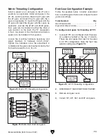
Figure 68. Power feed chart.
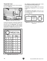
Figure 69. Power feed inner gear identification.
40T
Gear
Z2
L
Gear
Figure 70. Power feed outer gear identification.
40T
Gear
Z1
L
Gear
Z4
Install a spacer in the Z1 position, and install end
gears in the Z2, Z3, Z4, and L positions. Mesh
the Z2 gear with the Z3 gear, and mesh the Z4
gear with the L gear. Just like the Z1/Z2 and Z3/
Z4 gears, the L gear can be installed in either the
inner or outer position on the shaft. The "H" desig-
nation in the L row shown in the chart below indi-
cates a spacer is to be installed in that position.
Inch Threading Configuration
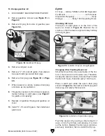
Figure 71. Inch TPI threading configuration.
B
A
C
8
16
32
9
18
36
10
20
40
11
22
44
12
24
48
13
26
52
14
28
56
90
45 40
70
H
H
H
H
H
H
H
H
H
H
H
H
H
80
80
80
80
60
65
60
70
70
70
55
80
40
40
30
40 70
75
75
50
50
55 50
60
Z Z
Z
Z
L
H
End Gear
Configuration
Feed Rate
Selectors
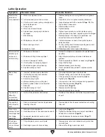
Figure 72. Inch end gear configuration.
L Position
Z2 Position
Z3 Position
Z4 Position
Loosen the mounting hardware necessary and
adjust backlash to between 0.002"–0.004".
Tighten the hardware once the adjustment is
complete and the gears are meshed correctly. Set
the feed rate selector to A, B, or C.
Z3
Summary of Contents for G0949G
Page 108: ......


