


-4-
Model G0899 (Mfd. Since 10/20)
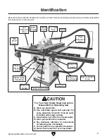
Controls &
Components
To reduce your risk of
serious injury, read this
entire manual BEFORE
using machine.
Refer to
Figures 1–3 and the following descrip-
tions to become familiar with the basic controls of
this machine.
A. ON/STOP Switch: Turns motor ON when
pulled out; turns motor
OFF when pressed in.
B. ON/STOP Switch Disabling Key: Disables
switch when yellow key is removed.
C. Handwheel Locks: Lock blade height
and angle when tightened (one on each
handwheel).
D. Blade Tilt Handwheel: Adjusts angle of
blade tilt from 90°–45°.
E. Blade Height Handwheel: Adjusts blade
height from 0"–3
1
⁄
8
".
F. Fence Lock Handle: Locks fence when
pushed down, unlocks fence when pulled up.
G. Fence: Guides workpiece as it moves into
blade and determines angle of cut. Fence
face can be positioned for standard cutting
operations, or placed in lower position for
blade guard clearance during narrow ripping
operations.
H. Fence Lock Knobs: Secure fence when
tightened; allow fence to be repositioned
along fence tube when loosened.
Figure 3. Location of fence controls.
G
F
H
Figure 2. Blade adjustment handwheels and
locks.
E
D
C
Figure 1. Location of ON/STOP switch.
A
B
Summary of Contents for G0899
Page 92: ......