background image

Model G0787 (Mfd. Since 09/14)

-9-

SECTION 2: POWER SUPPLY

Availability

Before installing the machine, consider the avail-
ability and proximity of the required power supply 
circuit.  If  an  existing  circuit  does  not  meet  the 
requirements for this machine, a new circuit must 
be installed. To minimize the risk of electrocution, 
fire,  or  equipment  damage,  installation  work  and 
electrical wiring must be done by an electrician or  
qualified service personnel in accordance with all 
applicable codes and standards.

Electrocution, fire, or 

equipment damage may 

occur if machine is not 

correctly grounded and 

connected to the power 

supply.

Full-Load Current Rating

The  full-load  current  rating  is  the  amperage  a 
machine draws at 100% of the rated output power. 
On  machines  with  multiple  motors,  this  is  the 
amperage drawn by the largest motor or sum of all 
motors  and  electrical  devices  that  might  operate 
at one time during normal operations.

Full-Load Current Rating at 120V .... 4.3 Amps

The full-load current is not the maximum amount 
of amps that the machine will draw. If the machine 
is overloaded, it will draw additional amps beyond 
the full-load rating.

If the machine is overloaded for a sufficient length 
of time, damage, overheating, or fire may result—
especially  if  connected  to  an  undersized  circuit. 
To  reduce  the  risk  of  these  hazards,  avoid  over-
loading  the  machine  during  operation  and  make 
sure it is connected to a power supply circuit that 
meets the specified circuit requirements.

For your own safety and protection of 

property, consult an electrician if you are 

unsure about wiring practices or electrical 

codes in your area.

Note: Circuit requirements in this manual apply to 
a dedicated circuit—where only one machine will 
be running on the circuit at a time. If machine will 
be connected to a shared circuit where multiple 
machines may be running at the same time, con-
sult an electrician or qualified service personnel to 
ensure circuit is properly sized for safe operation.

A  power  supply  circuit  includes  all  electrical 
equipment between the breaker box or fuse panel 
in the building and the machine. The power sup-
ply circuit used for this machine must be sized to 
safely handle the full-load current drawn from the 
machine  for  an  extended  period  of  time.  (If  this 
machine  is  connected  to  a  circuit  protected  by 
fuses, use a time delay fuse marked D.)

120V Circuit Requirements

This  machine  is  prewired  to  operate  on  a power 
supply circuit that has a verified ground and meets 
the following requirements:

Nominal Voltage .................... 110V, 115V, 120V

Cycle ..........................................................60 Hz

Phase ........................................... Single-Phase

Power Supply Circuit ......................... 15 Amps

Serious injury could occur if you connect 

the machine to power before completing the 

setup process. DO NOT connect to power 

until instructed later in this manual.

Summary of Contents for G0787

Page 1: ...NER S MANUAL For models manufactured since 09 14 COPYRIGHT FEBRUARY 2015 BY GRIZZLY INDUSTRIAL INC WARNING NO PORTION OF THIS MANUAL MAY BE REPRODUCED IN ANY SHAPE OR FORM WITHOUT THE WRITTEN APPROVAL...

Page 2: ...g grinding tool integrity and the usage of personal protective equipment The manufacturer will not be held liable for injury or property damage from negligence improper training machine modifications...

Page 3: ...CTION 4 OPERATIONS 16 Disabling Switch 16 Disc Sanding 17 Belt Sanding 18 Changing Replacing Sandpaper Disc 21 Changing Replacing Sanding Belt 22 Adjusting Belt Tracking 22 SECTION 5 ACCESSORIES 23 SE...

Page 4: ...call our Technical Support for help Before calling please write down the Manufacture Date and Serial Number stamped into the machine ID label see below This infor mation helps us determine if updated...

Page 5: ...functions as a guide for miter gauge K Angle Adjustment Knob Tightens to secure work table at desired angle L 21 2 Dust Port Connects to dust collection system not included A Belt Tensioning Lever Wh...

Page 6: ...pe Cardboard Box Content Machine Weight 41 lbs Length x Width x Height 23 x 12 x 13 in Must Ship Upright Yes Electrical Power Requirement 120V Single Phase 60 Hz Full Load Current Rating 4 3A Minimum...

Page 7: ...Left 0 Right 45 deg Table to Floor Height 4 3 4 in Construction Materials Base Cast Iron Table Die Cast Aluminum Frame Cast Iron Disc Aluminum Miter Gauge Plastic and Steel Paint Type Finish Urethane...

Page 8: ...of DANGEROUS ENVIRONMENTS Do not use machinery in areas that are wet cluttered or have poor lighting Operating machinery in these areas greatly increases the risk of accidents and injury MENTAL ALERTN...

Page 9: ...duce accidental contact with moving parts or flying debris Make sure they are properly installed undamaged and working correctly FORCING MACHINERY Do not force machine It will do the job safer and bet...

Page 10: ...lothes or hair getting entangled in sanding disc or belt Workpieces thrown by sander can strike nearby operators Long term respiratory damage can occur from using sander without proper use of a respir...

Page 11: ...circuit To reduce the risk of these hazards avoid over loading the machine during operation and make sure it is connected to a power supply circuit that meets the specified circuit requirements For y...

Page 12: ...rd size gets longer and the gauge size gets smaller higher gauge numbers indicate smaller sizes Any extension cord used with this machine must be in good condition and contain a ground wire and matchi...

Page 13: ...asses 1 Pair Screwdriver Phillips 2 1 Hex Wrench 6mm 1 Screwdriver Flat Head 2 1 Dust Collection System 1 Dust Hose 21 2 1 Hose Clamps 21 2 2 Needed for Setup Inventory The following is a list of item...

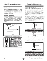
Page 14: ...the shop Below is the minimum amount of space needed for the machine Placement Location Bench Mounting Figure 7 Direct Mount setup Machine Base Workbench Lag Screw Flat Washer Another option is a Dire...

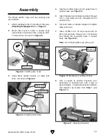
Page 15: ...washer on table lock knob as shown in Figure 9 Figure 9 Installing work table Table Lock Knob Washer Upper Hole Index Pin Threaded Hole Figure 8 Installing disc cover x 2 Disc Cover Assembly The Model...

Page 16: ...ose type and length between the dust col lector and the machine 3 number of branches or wyes and 4 amount of other open lines throughout the system Explaining how to cal culate these variables is beyo...

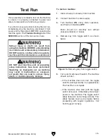
Page 17: ...EFORE understanding its controls and related safety information DO NOT operate or allow others to operate machine until the information is understood To test run machine 1 Clear all setup tools away f...

Page 18: ...prevent unsupervised operation always disable switch before leaving machine unattended Make sure to place key in a well hidden or secure location To reduce your risk of serious injury read this entire...

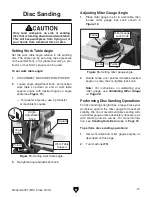
Page 19: ...forming Disc Sanding Operations For disc sanding straight lines always brace your workpiece against the miter gauge for maximum stability We do not recommend disc sanding with out a miter gauge unless...

Page 20: ...side along downward spinning half of sanding disc to prevent burning workpiece and excessive loading of sandpaper The Model G0787 disc sander can be used to sand convex outside curves Since the miter...

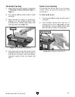
Page 21: ...ON and allow sander to reach full speed 3 Place workpiece on surface of sanding belt allowing it to rest against backstop Hold workpiece firmly and keep fingers away from sanding surface see Figure 1...

Page 22: ...in sander body see Figure 22 7 Set desired work table angle see Setting Work Table Angle on Page 17 and tighten table lock knob Figure 22 Installing work table on sanding bed Index Pin Slot Threaded...

Page 23: ...s sandpaper disc onto surface see Figure 24 Figure 24 Installing sanding disc 3 Remove remaining half of protective layer from sandpaper disc then press remaining portion of sandpaper disc onto alumin...

Page 24: ...ding belt moves away from disc toward back of machine rotate tracking knob coun terclockwise 1 4 turn 5 Turn machine ON then immediately turn machine OFF Sanding belt should be cen tered on drums and...

Page 25: ...ge To reduce this risk only install accessories recommended for this machine by Grizzly NOTICE Refer to our website or latest catalog for additional recommended accessories order online at www grizzly...

Page 26: ...very bit as import ant as a stable work surface this workbench is just what you need Includes six drawers with ball bearing slides and two lower compartments The end vise also includes two bench dogs...

Page 27: ...before adjustments maintenance or service Cleaning the Model G0787 is relatively easy Vacuum excess wood chips and sawdust and wipe off the remaining dust with a dry cloth If any resin has built up us...

Page 28: ...ressure 4 Workpiece crooked fence loose or misadjusted 5 Drive belt damaged and slipping 6 Dust collection ducting problem causing dust buildup 7 Dust collector undersized causing dust buildup 8 Motor...

Page 29: ...Sanding belt disc worn or damaged 1 Reduce pressure of workpiece against sanding belt disc 2 Use different stock or accept characteristics of stock and plan to clean replace sanding belt disc frequent...

Page 30: ...e and sanding disc to prevent the disc from rubbing against the table during operations Work table alignment should be checked and adjusted if necessary before each use or any time the work table is r...

Page 31: ...gure 35 Replacing Drive Belt To replace and tension drive belt 1 DISCONNECT MACHINE FROM POWER Drive Belt Housing Figure 36 Example of drive belt housing screws 4 Remove old drive belt and place new d...

Page 32: ...t at the time of printing but may not match your machine If you find this to be the case use the wiring diagram inside the motor junction box CAPACITORS INVERTERS Some capacitors and power inverters s...

Page 33: ...hind KEDU HY7 Relay WE 10 MOTOR Machine Housing Ground Ground Start Capacitor 100MFD 125VAC The wiring shown here was current at the time of printing but changes may occur over time Verify your machin...

Page 34: ...20 54 25 24 83 14 27 42 39 49 53 72 26 67 66 68 70 69 71 77 76 68 69 78 74 73 75 12 85 64 44 54 65 90 43 44 63 62 61 86 88 87 59 60 40 41 13 16 37 15 89 30 34 50 48 52 51 32 32 31 33 15 55 32 57 58 4...

Page 35: ...ECTRICAL BOX 68 P0787068 PHLP HD SCR M5 8 X 16 LH 23 P0787023 INSULATED SLEEVE 69 P0787069 LOCKING FLAT WASHER 5MM 24 P0787024 TOGGLE SWITCH 125 250V W KEY 70 P0787070 TIMING BELT 150XL037 25 P0787025...

Page 36: ...DESCRIPTION 93 P0787093 READ MANUAL LABEL 97 P0787097 ELECTRICITY LABEL 94 P0787094 BELT DISC ROTATION LABEL 98 P0787098 DISCONNECT 120V LABEL 95 P0787095 MACHINE ID LABEL 99 P0787099 GRIZZLY GREEN T...

Page 37: ...metalworker ____ 0 2 Years ____ 2 8 Years ____ 8 20 Years ____20 Years 6 How many of your machines or tools are Grizzly ____ 0 2 ____ 3 5 ____ 6 9 ____10 7 Do you think your machine represents a good...

Page 38: ...LINE FOLD ALONG DOTTED LINE GRIZZLY INDUSTRIAL INC P O BOX 2069 BELLINGHAM WA 98227 2069 Place Stamp Here Name_______________________________ Street_______________________________ City______________S...

Page 39: ...shall be tried in the State of Washington County of Whatcom We shall in no event be liable for death injuries to persons or property or for incidental contingent special or consequential damages arisi...

Page 40: ......

Reviews: