


Model G0699 (Mfd. Since 5/15)
-37-
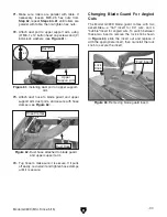
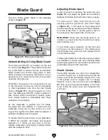
Changing Blade Guard For Angled
Cuts
The Model G0699 blade guard comes with two
assemblies—a "flat" insert for 90° cuts, and a
"bubble" insert for angled cuts. To switch between
these two inserts, remove the lock knob shown
in
Figure 63, slide the insert out and replace it
with the appropriate insert, then re-install the lock
knob to secure the insert.
Figure 63. Removing blade guard insert.
Lock
Knob
"Flat" Insert
71. Make sure rollers are parallel with table. If
necessary, loosen M20-2.5 hex nuts from
Step 62, repeat Steps 60–61 until rollers are
parallel with table, then re-tighten hex nuts.
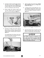
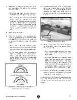
72. Attach dust port to upper support arm, using
(2) M6-1 x 12 button head cap screws and (2)
6mm lock washers (see
Figure 61).
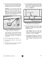
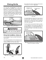
73. Attach dust hose to blade guard and upper
support arm dust ports, and secure with hose
clamps (see
Figure 62).
74. Tug hose to make sure it is secure. If it pulls
off easily, re-install it and tighten hose clamps
until it is secure.
Figure 62. Dust hose attached to blade guard
and upper support arm.
Dust Hose
Hose Clamps
Figure 61. Installing dust port on upper support-
arm.
x 2
Upper
Support Arm
Dust Port
Summary of Contents for G0699
Page 21: ...Model G0699 Mfd Since 5 15 19 5mm Hardware Recognition Chart...
Page 108: ......