Model G0699 (Mfd. Since 5/15)
-29-
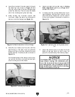
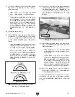
36. Loosen the fence clamp handle (see Figure
34), then slide the fence onto the T-slot plates
and the clamp plate so that the tall side of the
fence is facing the blade.
Figure 34. Installing the rip fence.
Rip Fence
Clamp Plate
Clamp
Handle
37. Slide the rip fence toward you, re-install the
stop screw that you removed in
Step 35,
move the fence forward until it stops, then
tighten the fence clamp handle.
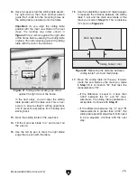
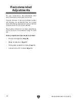
38. Insert the T-handle wrench into the left-hand
hole of the two shown in
Figure 35, engage
it with the scoring blade elevation bolt under
the table top, and rotate it counterclockwise
to lower the scoring blade below the table
surface.
Note: This will keep the scoring blade from
interfering with the rip fence alignment pro-
cess in the next steps.
Figure 35. Lowering the scoring blade.
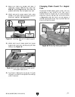
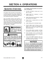
Figure 36. Rip fence against the saw blade.
39. Raise the main saw blade all the way up,
then slide the rip fence against it without
pushing on it, as shown in
Figure 36.
40. Loosen the fence rail hex nuts on both sides
and adjust the rail in or out until the rip fence
is even with the saw blade along its full
length, then hand-tighten the hex nuts again.
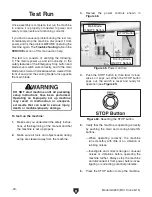
NOTICE
The rip fence body will scratch the table
and rear extension wing surfaces if the ride
height is not adjusted correctly.
Note:
The goal of the adjustments in the
next step is to make the rip fence body ride
height as close to and even with the table and
extension wing surfaces without touching or
scratching them.
Summary of Contents for G0699
Page 21: ...Model G0699 Mfd Since 5 15 19 5mm Hardware Recognition Chart...
Page 108: ......


