background image

Appendix A

Requirements according ISO 9869-1:2014

4.1

installed close to thermal bridges, cracks or similar sources of error
under direct influence of a heating or of a cooling device or under the draught of a fan

Rain
Snow
Direct solar radiation

Requirements according ISO 9869-1:2014

The standard ISO 9869-1:2014 states in section 6 how a measurement apparatus must be installed for proper
measurement and in section 7 how the measurement data must be analysed.
The ISO standard highlights the following important points for the 

installation

:

• Heat flux meters (HFM) and temperature sensors shall be mounted at a location 

that is representative

of the whole element (previous inspection using thermography cameras are mentioned).
• HFMs shall not be

• The outer surface of the element should be protected from

• Protection of the outer surface may be achieved through artificial screening.
• Data acquisition intervals should be less than 30min.

The analysis of the measurement data is separated into two methods. The first analysis method (the average
method) is introduced in section 7.1 of the standard. It is the method used in the current software. The
average method is valid if certain conditions are met:
• The heat content of the element is the same at the beginning and at the end of a measurement
(same temperatures and moisture distribution)
• The HFM is not exposed to direct solar radiation.
• False results might be obtained if the external face of the element is exposed to solar radiation
• The thermal conductance of the element is constant during the test

If the above conditions are not met, misleading results can be obtained. It is the responsibility of the user to
ensure that the conditions are met.
Data analysis (average method) for heavier elements with a specific heat per square meter greater than
20kJ/(m2K) according to section 7.1 shall be carried out over a period of integer multiple of 24h.

The measurement shall be ended only when the conditions are fulfilled as follows:
1. Duration of the measurement > 72h
2. R-value obtained at the end of the test does not deviate more than 5% from the value obtained 24h
before (dR24)
3. The R-value obtained during the first 2/3 of the overall measurement period (which needs to be an
integer of 24h, too) does not deviate more than 5% from the values obtained during the last 2/3 of the
overall measurement period (also an integer multiple from 24h).
4. The change in heat stored in the wall is <= 5% of the heat passing through the wall

While test conditions 1 – 3 are validated by greenTEG’s software, the condition 4 is not tested. greenTEG’s
measurement system does not allow measurement of heat storage changes of the wall. 

The appendix highlights key elements of the ISO 9869-1:2014 on which the data analysis of the
software is based. Even though the software is capable of analysing the measurement data, it is the
user of the system who has to ensure applicability of the ISO test conditions to measurement data.
The most important aspects for an ISO 9869 compliant U-value measurement are listed. For more
detailed information please refer to the complete ISO 9869 documentation.

18

Summary of Contents for GO MEASUREMENT SYSTEM II

Page 1: ...gOMS II greenTEG GO MEASUREMENT SYSTEM II USER MANUAL...

Page 2: ...CONTENTS I 01 02 03 04 OVERVIEW SET UP ANALYSING MEASUREMENTS APPENDIX...

Page 3: ...ag of Double Sided Adhesive Water Repellent Strips 1 Scissors 1 NOTE for customers who have purchased more than one pair of nodes For every extra pair purchased the products highlighted in green will...

Page 4: ...e for other sensors 1x combined heatflux surface temperature sensor 1x ambient air temperature sensor 1x surface temperature sensor 1x ambient air temperature sensor NODE INNER NODE TYPE 1 OUTER NODE...

Page 5: ...covered in a removable silicone sleeve The antenna should not be removed at any stage Press toggle button once to go to the next page of information within the same category Hold down the toggle butto...

Page 6: ...se Station Measurement has been instantaneously received from this node HF Heat Flux W m2 Ts Surface Temperature C T Ambient Temperature C A 1st Node Port B 2nd Node Port NODE INFORMATION MAIN MENU OV...

Page 7: ...Number Date and Time on next page INFO Node Overview Press toggle button to see individual node information MAIN MENU OVERVIEW Recording Status Press once to Start Stop Recording Hold down button for...

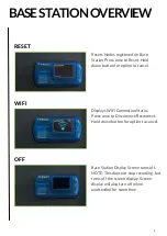
Page 8: ...Displays WiFi Connection Status Press once to Disconnect Reconnect Hold down button for option to cancel WIFI Base Station Display Screen turns off NOTE This does not stop recording but turns off the...

Page 9: ...01 02 03 04 OVERVIEW SET UP ANALYSING MEASUREMENTS APPENDIX CONTENTS 7...

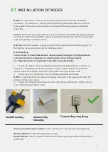
Page 10: ...e sided adhesive tape NOTE The instructions in this section are only a quick summary of node installation procedures It is necessary to read the gOMS II Mounting Recommendations manual for more detail...

Page 11: ...s is suitable when you have a maximum of 10 nodes in your environment Option 2 Manually Enter the Serial Numbers S N of the nodes for pairing This number is found on the front of your nodes Once your...

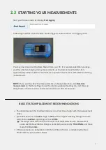
Page 12: ...Autonomous Battery Life is approximately 48 hours Below the minimum required 72 hours for an ISO 9869 conforming measurement BASE STATION PLACEMENT RECOMMENDATIONS The ideal placement for the Base Sta...

Page 13: ...CONTENTS 12 01 02 03 04 OVERVIEW SET UP ANALYSING MEASUREMENTS APPENDIX...

Page 14: ...ecording you will be given the option to end the measurement You can only analyse reports of measurements that have ceased recording A list of all recorded measurements stored on the Base Station will...

Page 15: ...te the starting measurement Date and Time and the ending measurement Date and Time Select the Measurement Period that you wish to analyse This can be done by either manually entering the time at the t...

Page 16: ...ighlighted in Bold Underneath these values the ISO conformity is displayed You can select and deselect which values you would like displayed on the graph with the legend on the righthand side of the g...

Page 17: ...MEAUSUREMENT Non Conforming ISO Measurements 3 3 If your measurement is not conforming to the ISO 9869 standard it will be displayed as seen below The reason for non conformity is displayed upon repor...

Page 18: ...CONTENTS 17 01 02 03 04 OVERVIEW SET UP ANALYSING MEASUREMENTS APPENDIX...

Page 19: ...xposed to solar radiation The thermal conductance of the element is constant during the test If the above conditions are not met misleading results can be obtained It is the responsibility of the user...

Page 20: ...69 compliant U value In this case a multitude of 24h is recommended on top of the 72h time period Mounting of the surface temperature sensor and the combined surface temperature heat flux sensor Mount...

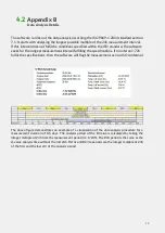
Page 21: ...specifications If no interval 72h fulfils the specifications then the software will flag the measurement as non ISO conformal The above figure demonstrates an example of a visualization of the data a...

Page 22: ...Appendix C Detailed explanations of the parameters used in the report 4 3 21...

Page 23: ...wish to change to ten minutes follow this step Elsewise proceed to step 2 Measurements can be taken every 1 minute or every 10 minutes This can be changed by the user To change the measurement freque...

Page 24: ...Revision history greenTEG AG Hofwisenstrasse 50a CH 8153 R mlang Z rich www greenteg com info greenteg com 41 44 515 09 15 copyright all rights reserved greenTEG 2022 22...

Reviews: