Node Mounting:
For a U-Value / R-Value Measurement, mount an inner node (type 1) configuration and
outer node (Type 2) configuration on opposite sides of your building element.
See "Nodes Overview" at beginning of manual for more information.
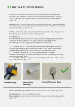
1. Mount the node to the wall using the provided double-sided adhesive roll tapes, or
place it on a suitable spot next to the wall (for example a shelf). Please ensure that the
adhesive tape removal tabs stick out from the side of the measurement node.
2. Mount the Inner sensor with a strip of double-sided adhesive roll tape.
NOTE
: It is important that the removal tab points to the side of the sensor and not to the
direction of the sensor cable.
3. Mount the ambient air temperature sensor using the provided sensor holder and one
piece of double-sided adhesive tape.
NOTE:
The instructions in this section are only a quick summary of node installation
procedures. It is necessary to read the gOMS II Mounting Recommendations manual for
more detailed instructions and precautions on all gOMS mounting options provided by
greenTEG.
Caution:
Sensor accuracy only performs as per specifications if greenTEG mounting solutions
are used. Any other non-greenTEG approved mounting solutions will result in measurement
errors and possibly even safety issues.
Optional:
Use thermographic imaging to help identify representative/interesting spots for
the heat flux sensor placement on your building element
2.1
Note for various Mounting Conditions:
Further instructions are available in the Mounting Guide.
Wet Conditions:
Use the mounting strips provided
Rough Surfaces:
Mount the node at the wall with thermal putty (Available on Request from
greenTEG).
Node Mounting
Ambient Clip
Mounting
Correct Mounting Setup
INSTALLATION OF NODES
9
Summary of Contents for GO MEASUREMENT SYSTEM II
Page 1: ...gOMS II greenTEG GO MEASUREMENT SYSTEM II USER MANUAL...
Page 2: ...CONTENTS I 01 02 03 04 OVERVIEW SET UP ANALYSING MEASUREMENTS APPENDIX...
Page 9: ...01 02 03 04 OVERVIEW SET UP ANALYSING MEASUREMENTS APPENDIX CONTENTS 7...
Page 13: ...CONTENTS 12 01 02 03 04 OVERVIEW SET UP ANALYSING MEASUREMENTS APPENDIX...
Page 18: ...CONTENTS 17 01 02 03 04 OVERVIEW SET UP ANALYSING MEASUREMENTS APPENDIX...
Page 22: ...Appendix C Detailed explanations of the parameters used in the report 4 3 21...


