background image

45

AIRSCOUT ENTERPRISE CLOUD USAGE

There are two types of roles available for users of AirScout Enterprise in the cloud: 
vendor administrators and technicians. Vendor administrators may access license 
information and create new technician accounts in addition to viewing reports generated 
by all technicians under them.
To access the cloud, point your browser to:
https://airscoutenterprise.textron.com 
and use your credentials to get logged in.

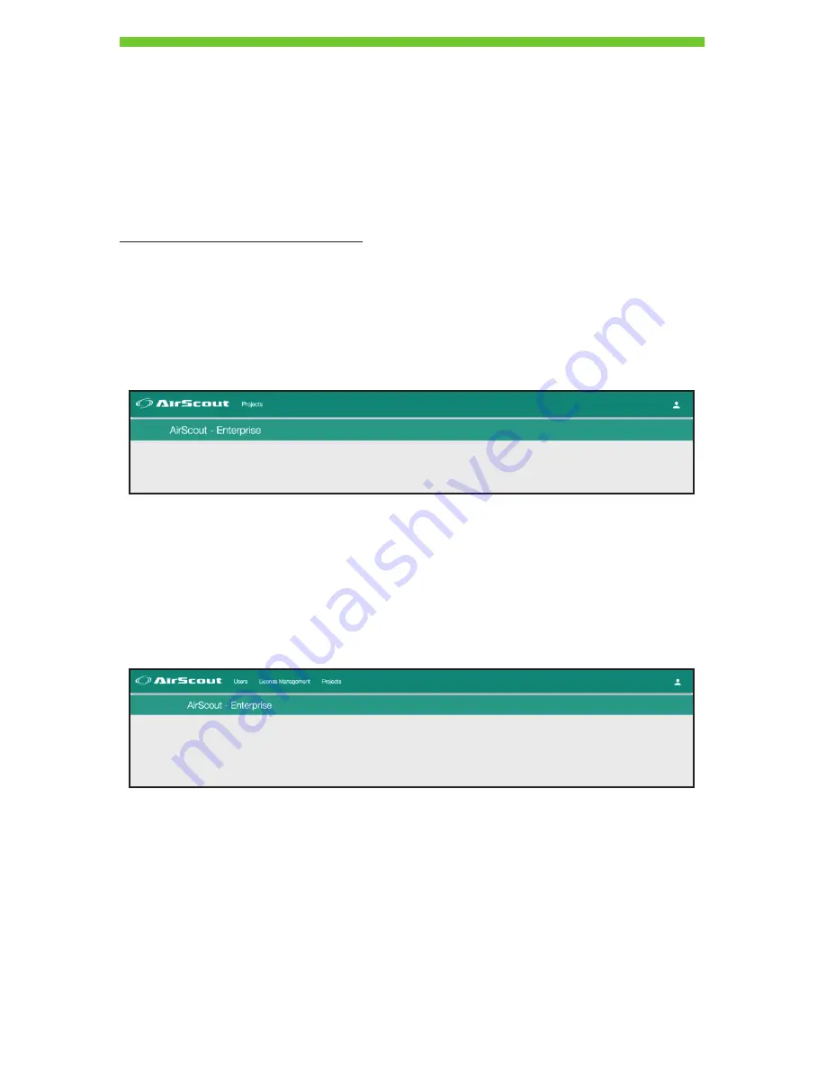
Technician Portal

The technician portal can be accessed by logging in with technician credentials.
For a regular technician the portal will show a list of projects assigned to or started by 
them.

They may access existing projects they have defined along with all results generated from 
any tests belonging to those projects.

Vendor Administrator Portal

Vendor administrators have the ability to manage users (technician(s)/other vendor 
admin(s) for the same subscription). A vendor administrator can view projects/reports 
created by all users that have been linked to their account.

DRAFT #2—11.16.16

Summary of Contents for AirScout Enterprise

Page 1: ...AirScout Enterprise Instruction Manual new number 2016 Greenlee Textron Inc 11 16 DRAFT 2 11 16 16 ...

Page 2: ...Pairing Clients to a Master 15 Un pairing Clients from a Master 15 APPLICATION USE 16 Firmware Updates 16 Creating a Cloud Account and Setting Up a License 19 Logging in 20 Adding a Project 21 Adding a Building 21 Adding a Floorplan 22 Selecting Test Parameters 30 Connecting AirScout to the Application to Run the Test 31 Running a Validate New Network Test with the Master as AP 37 Running a Valida...

Page 3: ...nual and any markings on the tool provide information for avoiding hazards and unsafe practices related to the use of this tool Observe all of the safety information provided Do not discard this product or throw away For recycling information go to www greenlee com All specifications are nominal and may change as design improvements occur Greenlee Textron Inc shall not be liable for damages result...

Page 4: ...turn on red while at least one unit is charging The LED will turn green when charging is complete Specifications Power input Carry case 11 to 15 VDC 2 5 A maximum AirScout Master Controller 300 ASM300 11 to 15 VDC 1 A AirScout Client 300 ASC300 5 00 0 5 V 1 A Operating temperature 0 to 60 C 32 to 140 F Charging temperature 10 to 55 C 14 to 131 F Operating humidity 90 max non condensing Storage tem...

Page 5: ... CAUTION Risk of explosion if battery is replaced by an incorrect type Dispose of used batteries according to the instructions This battery is not serviceable by the customer The lithium polymer cell was tested in accordance with UL2054 and IEC 62133 and it has a capacity below 15 7 Wh If service is required contact Greenlee for your nearest authorized repair center The battery must be recycled or...

Page 6: ...erference and This device must accept any interference including interference that may cause undesired operation EU Compliance Greenlee Textron Inc hereby declares that the AirScout kit is in compliance with the essential requirements and other relevant provisions of Directive 1999 5 EC and the R TTE Directive A copy of the full Declaration of Conformity may be downloaded from www greenleecommunic...

Page 7: ...0 master The master is a compact battery powered 802 11 Wi Fi access point AP test device providing a premises wide solution for optimizing Wi Fi installations and diagnosing Wi Fi problems The master coupled with client devices provides a client side view of the Wi Fi network simultaneously measuring signal quality congestion interference and application level performance throughout the entire pr...

Page 8: ...s with the master AirScout can simultaneously test a premises using one to 30 client devices providing needed coverage throughout the premises 1 2 3 4 5 6 1 Device Status LED 2 Power Status LED 3 Identification Button 4 Power Button 5 Pairing Button 6 Micro USB Power Input Client Front View Client Rear View DRAFT 2 11 16 16 ...

Page 9: ...t is installed with the InstallShield Wizard While all attempts have been made to include the installer with all the required application dependencies it is important to remain connected to the Internet during this process in case other dependencies need to be installed The installation procedure is similar to installing any other Microsoft Windows application 1 Start the installer by double click...

Page 10: ...installer might reboot your computer to finish installing these dependencies Upon reboot the installer launches automatically and continues the installation 4 Press Next to continue installation DRAFT 2 11 16 16 ...

Page 11: ...5 The installer now shows you details regarding the installation including the installation location When you select Install the installer begins copying files to complete the installation DRAFT 2 11 16 16 ...

Page 12: ...pletion the installer indicates it has finished installation Select Finish to complete installing the application 7 The installer creates a desktop shortcut with which you can launch the application DRAFT 2 11 16 16 ...

Page 13: ...harging can occur while the unit is on or off Device Status LED The device status LED is located on the left side of both master and client devices 1 White solid indicates the device is powering up 2 Off indicates the client and master are not connected client is not paired to a master client is out of radio range from the paired master master is not connected to any client devices 3 Green solid i...

Page 14: ...o the rear label of the master to identify the SSID and Password necessary to connect your tablet or PC to AirScout 1 On the tablet or PC navigate to the Wi Fi settings menu 2 Ensure Wi Fi is enabled 3 From the available networks select the SSID of the master 4 Once the tablet or PC is connected the AirScout SSID appears in the connected list DRAFT 2 11 16 16 ...

Page 15: ...t devices pair to the correct master only pair one AirScout solution at a time if AirScout kits are within radio range of each other The client cannot discriminate between two masters that are both in pairing mode Prior to pairing ensure that the client and master devices are in close proximity and the battery is not low 1 Ensure all devices are powered on and the right side power status LED is gr...

Page 16: ...all client devices are connected to the master The latest firmware is automatically downloaded to the BYOD from the cloud based on the user that is logged in and their licensing permissions To view update the firmware on the ASM300 and ASC300 devices follow these steps 1 Press the Firmware button located in the upper right corner of the application The Badge indicates that there is a firmware upda...

Page 17: ...p to date are shown in green Devices that can be updated to more recent firmware are shown in orange Gray devices are paired clients that are currently not connected or powered on 4 To update the connected devices press the Start button DRAFT 2 11 16 16 ...

Page 18: ...18 5 The progress of the update is shown 6 After the update is complete AirScout displays client device and firmware status DRAFT 2 11 16 16 ...

Page 19: ...ving as a technician The technician may sign up without a vendor administrator email for a trial license but this will be required after the trial expires Next for technician roles enter the vendor administrator email address if known If not this can be left blank for a trial license Then fill out the remaining form to finalize the account setup The email address entered will be used for validatio...

Page 20: ... if you are still logged in to the system as the super admin Logging in For login the BYOD should always be connected to the Internet However after the first login attempt the credentials are cached on the application and the user will not be required to log in again upon the next application launch Launch the application on the BYOD and use the recently created account to log in In the applicatio...

Page 21: ... with two input fields Enter the Project Work Order Number and Project Name and press ADD PROJECT The Project Work Order Number can be numeric or alphanumeric Important Project Work Order Number must be unique Adding a Building To add a building inside an existing project press the button which is located at the top right corner below the User and Firmware buttons The button is highlighted in a re...

Page 22: ...ect setup page Click the ADD ANOTHER BUILDING button to create multiple buildings Adding a Floorplan Add a floorplan only inside an existing building Select an existing building or create a new one After opening the building there is an Add Floorplan button Hover the mouse over the button to reveal the various options to import the floorplan onto the building DRAFT 2 11 16 16 ...

Page 23: ... to the selected floorplan view There is tool box to the right of the screen To add a door click on the icon and then drag and drop it on the floorplan To add an elevator click on the icon and then drag and drop it on the floorplan To add stairs click on the icon and then drag and drop it on the floorplan To rotate the floorplan 90 clockwise click on the icon After making the necessary changes cli...

Page 24: ...lans to import the floorplan After the user has successfully signed in the files png jpg and pdf and folders available in the user s dropbox are shown in the Import from Dropbox pop up Select the required floorplan file and click the Use This button to import the floorplan The user can also select files from the Shared Folder by selecting the shared option DRAFT 2 11 16 16 ...

Page 25: ...other step where the user has to give permissions to the application After the user has successfully signed in the files png jpg gif and pdf and folders available in the user s dropbox are shown in the Import from Google Drive pop up Select the required floorplan file and click the Use This button to import the floorplan The user can also select files from the Shared Folder by selecting the shared...

Page 26: ...f the floorplan Note This process is not needed when importing the floorplan from the Greenlee Builder option A green lined selection box appears on the floorplan The user may change the size by dragging the green dots which are at every corner of the selection box After adjusting the size of the selection box click on the CROP button to crop the floorplan The cropped floorplan is displayed on a n...

Page 27: ...ion to define a boundary The user may define a boundary by tapping the vertices representing the boundary of the floorplan to be considered in the analysis This process helps to provide a more precise mapping of coverage while improving the accuracy of the recommended AP placement for the floor Once finished defining the area of the boundary click on the square icon to permanently set the boundary...

Page 28: ...or click CANCEL to close the pop up window and return back to the floorplan The user will be prompted to set the scale for the floorplan after the cropping process has been completed The user is then prompted with a pop up message stating Measure the wall or surface then drag and drop your cursor along the image to set the image scale Click OK to move on to set the scale DRAFT 2 11 16 16 ...

Page 29: ...other in the floorplan After the mouse cursor has been dropped a pop up window appears for entering the scales in imperial or metric system After entering the scales click the TEST NOW button to continue to the Set Test Parameters section DRAFT 2 11 16 16 ...

Page 30: ...e button is on when it turns green This measurement is sufficient to recommend optimal placement but will not provide throughput capacity analysis Slide the toggle button labeled Measure Capacity to the right to choose the measurements of TCP Downstream and Ping Access Point This measurement option provides throughput capacity analysis but takes longer than just measuring for coverage Parameters t...

Page 31: ...new dialog box to instruct the connection of AirScout to the BYOD Pressing CANCEL redirects to the set scale page Connecting AirScout to the Application to Run the Test Validate New Network Test Testing a New Network with the Master as AP After setting up the test parameters and selecting the Validate New Network option the user is taken to a new screen where status of the connection between maste...

Page 32: ...er device is not found a warning message is displayed Click on icon to display additional information on how to connect to the master device Click the GOT IT button to go back to the previous screen DRAFT 2 11 16 16 ...

Page 33: ...etworks may require additional Information Technology IT expertise to assist with connecting AirScout to the network For this test the master needs to be connected via Ethernet to the existing network infrastructure and be able to obtain a local IPv4 address on the LAN via the Dynamic Host Configuration Protocol DHCP while maintaining a fully available bi directional Internet Protocol IP route bet...

Page 34: ...ectly to master on same LAN segment AirScout master connected to Switch 1 AirScout gets IP address from DHCP server on Switch 1 or other server on the LAN segment Access points fully reachable and routable to the master on Switch 1 and Switch 2 via Bridge or VLAN trunk to pass traffic between them as needed Clients who join access points connected to any switch can send packets directly to master ...

Page 35: ... of the connection between Master and BYOD is shown Note that this screen is different from the case where the master is being used as a surrogate AP It is important to follow the process to provision the clients to ensure success during this process 1 First bring the master clients and BYOD into the area where the wired connection will be available for the master to connect via Ethernet 2 Then ma...

Page 36: ...the message in the pop up window e g Bajra Mac in the case for the image below After the connection has been established a message appears stating Now Master is connected via AP and both the messages above have green check marks indicating the user can continue to the Test page DRAFT 2 11 16 16 ...

Page 37: ...page The master appears as a black AirScout device with a blue diamond Physically move the master to the point on the floor where the icon indicates on the floorplan For best results it is ideal to place the master as high as possible using a pedestal or temporarily mounting to the ceiling as the RF coverage is maximized To add clients to the floorplan press the ID button on any client device for ...

Page 38: ...ion on client placement The user can place the master in the location denoted by AP in the figure below suggested by the application Similarly the white dots are the suggested location for the clients The suggestion appears according to the scale set for the floorplan After placing the master and clients press the orange Start Test button near the bottom right of the floorplan to start the test A ...

Page 39: ...f there are more areas to test that contain additional blockages or other impairments to signal Click Continue to test additional locations to run another test by placing the master in a new AP location and placing the clients in new locations By pressing Accept the test result as finished the current results are saved and the test is considered complete Once saved the application redirects to the...

Page 40: ... icon AP and drag and drop it on the floorplan page The access point appears as a circular wireless radio icon Continue dragging access points to the floorplan to match the number that are deployed on the floor To add clients to the floorplan simply press the ID button on any client device for a moment until the left side LED on the top cover starts flashing purple The ID button is located left of...

Page 41: ...ype of test can improve the resolution of the heatmap or broaden the range covered if there are more areas to test that contain additional blockages or other impairments to signal By pressing Accept the test result and finished the current results are saved and the test is considered complete Once saved the application redirects to the report page to view the results Moving Between Locations Durin...

Page 42: ...he left side menus for Data Type and Build Your Own Analysis are shown Heatmap Metrics and Pass Fail Criteria Heatmaps are drawn based on the selected metric within the Build Your Own Analysis tab In the upper left corner of the heatmap area the user can see information related to the current heatmap metric shown In addition the analysis engine provides a method to define pass fail criteria for in...

Page 43: ...tmap will redraw the red yellow green areas This is especially useful in performing margin analysis The heatmap threshold value for different measurements is defined for the following range Signal strength 1 dBm to 100 dBm Latency 1 ms to 1000 ms SNR 1 dB to 100 dB Throughput heatmaps are based on the measured value by the client for different device classes and traffic types The pre defined traff...

Page 44: ...indicates a black dot on the heatmap where the client is located A failing measurement is shown by a red dot within the black dot for the client location The criteria for passing failing for the various metrics is defined as follows For signal strength RSSI If RSSI threshold value PASS If RSSI threshold value FAIL For throughput If throughput threshold value PASS If throughput threshold value FAIL...

Page 45: ...entials to get logged in Technician Portal The technician portal can be accessed by logging in with technician credentials For a regular technician the portal will show a list of projects assigned to or started by them They may access existing projects they have defined along with all results generated from any tests belonging to those projects Vendor Administrator Portal Vendor administrators hav...

Page 46: ... add buildings or run additional tests but a project with Closed status will not allow additional buildings or tests to be added to the project Click SAVE to save changes To access project tests or buildings click n buildings where n refers to the number of buildings in the project In the example above there is one building defined Note that other floors may be added to the building by clicking Ad...

Page 47: ...xt page which categorizes the test types into Coverage Capacity or Optimization You may also click on Client Pass Fail Report to go to the result viewer which resembles to the one found in the AirScout application Coverage tests include Signal Strength RSSI and Access Point survey tests that contain information on the other existing WiFi networks detected during the test Capacity tests include thr...

Page 48: ...he report The report can be 1 Viewed as a HTML document on the browser itself 2 Viewed as a PDF document 3 Downloaded onto the device 4 Sent to any valid email address as an attachment If the size of the report is higher than 10 megabytes a public link will be sent to the specified email address Upon clicking Send a dialog box to send PDF reports to any email address appears You may send the repor...

Page 49: ... vendor 3 Project reports for each and every report generated by technicians To manage users click on the Users link on the navigation bar If there are no users click to add one A vendor admin may create vendor administrators or technicians If a vendor administrator is created the newly created vendor administrators have equal privileges to its creator the old vendor administrator DRAFT 2 11 16 16...

Page 50: ...that the project is incomplete and may be edited Accessing Editing Prior Projects You can edit the project name and status by clicking on the pencil icon Projects can be deleted by pressing on the trash can icon The count of buildings that belong to a project is shown right under the project name Following the link leads to the Buildings page for that project The Building page displays each buildi...

Page 51: ... and is connected to the Wi Fi network AirScout XXXXXX where XXXXXX is the last six digits of the master MAC address 2 Firmware may not be up to date Please check the firmware updater page in the application to see if the master and clients are up to date 3 Restart the device application master and clients by power cycling and attempt to reconnect to the AirScout SSID once the restart is complete ...

Page 52: ...that the master clients and application device are present in the same area within range of the master s Wi Fi signal and that the application is currently connected to the AirScout SSID 2 Ensure that the master is plugged into the access point network and maintains an IP route in both directions for all access points connected to the network a If there is not a route available due to access contr...

Reviews: