Indirect Gas-Fired Heat Modules
3
Table of Contents
General Safety Information . . . . . . . . . . . . . . . . . . . . 1
Receiving, Unpacking, Storage . . . . . . . . . . . . . . . . . 2
Unit Identification . . . . . . . . . . . . . . . . . . . . . . . . . . . . 2
Furnace Model Number . . . . . . . . . . . . . . . . . . . . . . . 2
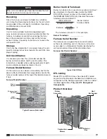
Burner Control Turndown . . . . . . . . . . . . . . . . . . . . . 2
Furnace Serial Number . . . . . . . . . . . . . . . . . . . . . . . 2
ETL Listing . . . . . . . . . . . . . . . . . . . . . . . . . . . . . . . . . 2
Product Overview . . . . . . . . . . . . . . . . . . . . . . . . . . . . 2
Furnace Control Center
Furnace Control Center Components . . . . . . . . . . 4
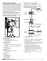
Typical Furnace Control Logic . . . . . . . . . . . . . . . . 4
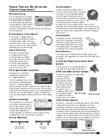
Typical Furnace, Electrical and
Control Components
. . . . . . . . . . . . . . . . . . . . . . . 5
Gas-Fired Burner Turndown
. . . . . . . . . . . . . . . . . 6
Electronic Modulation . . . . . . . . . . . . . . . . . . . . . . . 6
Two Stage Valve . . . . . . . . . . . . . . . . . . . . . . . . . . . . 6
Combinations . . . . . . . . . . . . . . . . . . . . . . . . . . . . . . 6
Available Turndown Control Options . . . . . . . . . . 6
Installation of Venting for Outdoor Units
. . . . . . 7
Installation of Venting for Indoor Units
. . . . . . . . 7
Venting Methods . . . . . . . . . . . . . . . . . . . . . . . . . . . 8
Installation of Standard Indoor Venting
Horizontal . . . . . . . . . . . . . . . . . . . . . . . . . . . . . . . . . 8
Vertical . . . . . . . . . . . . . . . . . . . . . . . . . . . . . . . . . . . 8
Installation of Concentric Venting
Horizontal . . . . . . . . . . . . . . . . . . . . . . . . . . . . . . . 9-10
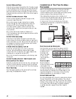
Vertical . . . . . . . . . . . . . . . . . . . . . . . . . . . . . . . . 10-11
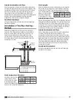
Two-Pipe Venting - Horizontal . . . . . . . . . . . . . 11-12
Two-Pipe Venting - Vertical . . . . . . . . . . . . . . . . . . 12
Installation of Control Wiring
. . . . . . . . . . . . . . . 13
Installation of Discharge Air Sensor
. . . . . . . . . 13
Installation of Gas Piping
. . . . . . . . . . . . . . . . . 13-14
Gas Supply Requirements. . . . . . . . . . . . . . . . . . . 14
Connect the Supply Gas Line . . . . . . . . . . . . . . . . 14
Installation Addition Regulator . . . . . . . . . . . . . . . 14
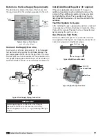
Testing the System for Leaks . . . . . . . . . . . . . . . . 14
Gas Pressure Test Ports . . . . . . . . . . . . . . . . . . . . 14
Sequence of Operation
. . . . . . . . . . . . . . . . . . . . . 15
Start-Up / Standby . . . . . . . . . . . . . . . . . . . . . . . . 15
Heat Mode . . . . . . . . . . . . . . . . . . . . . . . . . . . . . . . 15
Recovery from Lockout . . . . . . . . . . . . . . . . . . . . . 15
Performance Dat
a . . . . . . . . . . . . . . . . . . . . . . . . . 15
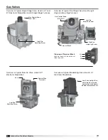
Gas Valves
. . . . . . . . . . . . . . . . . . . . . . . . . . . . . . . . 16
Start-Up - Furnaces (all units)
. . . . . . . . . . . . . . . 17
4:1 Turndown Electronic Modulation . . . . . . . . . . 17
Adjust High Fire and Low Fire Settings . . . . . . . 18
Modulating Valve High Fire Setting . . . . . . . . . . 18
Modulating Valve Low Fire Setting . . . . . . . . . . 18
2:1 Turndown Electronic Modulation . . . . . . . . . . 19
8 Stage Combustion . . . . . . . . . . . . . . . . . . . . . . . 20
Single Stage . . . . . . . . . . . . . . . . . . . . . . . . . . . . . . 20
2 Stage Combustion . . . . . . . . . . . . . . . . . . . . . . . 21
Combination Turndown Configurations . . . . . . . . 21
Troubleshooting
Ignition Controller . . . . . . . . . . . . . . . . . . . . . . . . . 22
4:1 Electronic Modulation . . . . . . . . . . . . . . . . . 23-24
2:1 Electronic Modulation . . . . . . . . . . . . . . . . . . . 25
8 Stage . . . . . . . . . . . . . . . . . . . . . . . . . . . . . . . . 26-27
Single and Two Stage . . . . . . . . . . . . . . . . . . . . . . 28
Reference: FX Controller
. . . . . . . . . . . . . . . . . . . 29
Stand-alone Furnace Control . . . . . . . . . . . . . . . . 29
Program Mode . . . . . . . . . . . . . . . . . . . . . . . . . . 29
Inlet Air Sensor (optional) . . . . . . . . . . . . . . . . . . 29
Discharge Air Temperature . . . . . . . . . . . . . . . . . 29
Outside Air Temperature . . . . . . . . . . . . . . . . . . . 30
Go to High Fire Mode . . . . . . . . . . . . . . . . . . . . . 30
Return to Normal Operation . . . . . . . . . . . . . . . . 30
Access to Set Points Menu . . . . . . . . . . . . . . . . 30
Access the Discharge Air Temperature . . . . . . . 30
Access the Inlet Air Sensor (optional) . . . . . . . . 30
Access the Room Override Setting . . . . . . . . . . 30
Furnace Control with Microprocessor . . . . . . . 30-31
Maintenance
Combustion Blower Motor . . . . . . . . . . . . . . . . . . 31
Burners and Orifices . . . . . . . . . . . . . . . . . . . . . . . 31
Heat Exchanger . . . . . . . . . . . . . . . . . . . . . . . . . . . 31
Flue Collector Box . . . . . . . . . . . . . . . . . . . . . . . . . 31
Electrical Wiring . . . . . . . . . . . . . . . . . . . . . . . . . . . 31
Gas Train . . . . . . . . . . . . . . . . . . . . . . . . . . . . . . . . 31
Replacement Parts . . . . . . . . . . . . . . . . . . . . . . . . 31
Maintenance Log
. . . . . . . . . . . . . . . . . . . .Backcover
Our Commitment
. . . . . . . . . . . . . . . . . . . .Backcover
®


