background image

Indirect Gas-Fired Heat Modules

29

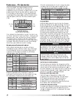
The controller has four buttons, one for “Function”, one 
for “Enter” and two for “Up” and “Down”. During normal 
operation, the screen will show the version number of 
the program that is installed in the FX controller. The 
version number typically consists of a letter followed by 
two digits. Press Up or Down arrows to scroll through 
main menu, press Enter for numeric reading.

Stand-alone Furnace Control

Units without microprocessor controls will have a 
standalone furnace controller. In this case, all the logic 
for controlling the furnace is contained within the FX 
controller. On this type of controller, the LED status 
indicator lights show the following:

When the controller is first turned on, or after 10 
seconds of inactivity by the user, the display will show 
the main menu. The items in the main menu are:

Reference - FX Controller

The FX controller is a programmable electronic 
controller that is used on the 4:1 electronically 
modulated furnace and the 8:1 staged furnace. It is pre-
programmed at the factory and normally requires few 
or no changes to the settings. It has a digital readout 
consisting of three large digits and three smaller status 
indicator lights at the top. The status indicator lights 
show:

Controller Interface 

Key Function Description

Function

Enter

Down

Up

LED Status Indicators

If the FX controller detects a fault, it will go into alarm 
condition and a message code will appear on the 
screen. Message codes that may appear include:

Program Mode

Program Mode allows the user to view the Program 
Menu and edit the factory default settings. To access 
Program Mode and view the Setpoints Menu, press 
and hold the Function button for three seconds. While 
viewing the Setpoints Menu, press the Up or Down 
buttons to scroll through the menu options. To view 
the setting of the selected menu option, press the 
Enter button. To edit the setting, press the Up or Down 
buttons while viewing the setting. To save the new 
setting and return to the Setpoints Menu, press the 
Enter button. To return to the Setpoints Menu without 
saving the change, wait 15 seconds. To exit Program 
Mode from the Setpoints Menu, wait for 15 seconds.

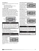
Inlet Air Sensor (iAS) (optional)

The Inlet Air Sensor monitors the temperature of the 
inlet air. If the inlet air is above the setpoint, the inlet air 
sensor shuts off the furnace and continues to supply 
the warm outside air. The inlet air sensor is preset to the 
factory-recommended 65°F for 8 stage furnaces and 
60°F for 4:1 turndown modulated furnaces.

Discharge Air Temperature (dtS)

The Discharge Air Temperature setting is the 
temperature the unit will discharge. The Discharge 
Air Temperature setting is preset to the factory-
recommended 70°F. The actual discharge air 
temperature can be displayed by pressing the Up or 
Down button from the default screen.

Outside Air Temperature (OAt)

To temporarily display the outside air temperature, press 
the Up or Down buttons from the default screen to 
change the display until “OAt” is displayed, then press 
the Enter button.

WARNING

Changing the default settings will significantly affect 
performance. Only change a setting after reading and 
understanding this entire manual. Before changing 
any settings, write down the factory-installed setting.

NOTE

The Enter button must be pressed to save any 
changes made to the settings. If the Enter button 
is not pressed, the unit will default back to the last 
saved setting.

Display Text

Significance

FXX

Default display

##

Discharge air temperature 

oAt

Outdoor air temperature

Sot

Discharge air temperature setpoint by 

Microprocessor input

rCt

Discharge air temperature by room 

command module

LED 

Position

Status

Significance

Left

Off

No call for heat

On

Call for heat

Blinking

High fire task is on

Middle

Off

Furnace is off

On

Furnace is on

Blinking

High fire task is on

Right

Off

High speed combustion fan is off

On

High speed combustion fan is on

Blinking

High fire task is on

Display Text

Significance

FXX

Controller has returned to normal status

dtI

Discharge air temperature is invalid

otI

Outdoor air sensor is invalid

HIF

High fire task

AFF

Air flow fault

®

Summary of Contents for PVF

Page 1: ...l building codes installation must conform to the National Fuel Gas code ANSI Z223 1 or in Canada CAN CGA B149 Installation codes All electrical wiring must be in accordance with the regulations of the National Electric Code ANSI NFPA 70 Unit is approved for installation downstream from refrigeration units In these conditions condensate could form in the duct furnace and provision must be made to ...

Page 2: ... Unit Identification It is necessary to know the unit model number the burner control turndown and the serial number This information is needed when ordering replacement parts and is available on labels located on the unit Furnace Model Number On the furnace access door or immediately next to the door is a Mylar data label See image below Locate the furnace model number at the top of the label and...

Page 3: ...r Leaks 14 Gas Pressure Test Ports 14 Sequence of Operation 15 Start Up Standby 15 Heat Mode 15 Recovery from Lockout 15 Performance Data 15 Gas Valves 16 Start Up Furnaces all units 17 4 1 Turndown Electronic Modulation 17 Adjust High Fire and Low Fire Settings 18 Modulating Valve High Fire Setting 18 Modulating Valve Low Fire Setting 18 2 1 Turndown Electronic Modulation 19 8 Stage Combustion 20...

Page 4: ...ff igniter Typical Furnace Control Logic In all cases refer to the unit specific wiring diagram located on the unit control center door This illustration is only for a typical 4 1 turndown electronic modulation configuration Temperature Sensor If there is no DDC the sensor is connected to the FX DDC Located in unit main control center FX Controller Input Converter Ignition Controller Call for heat ...

Page 5: ... The temperature dial and amplifier are installed in the furnace control center Field adjustments include discharge air temperature which is done by means of the Remote Temperature Dial Amplifier Remote Temperature Dial Typical Furnace Electrical and Control Components Microprocessor The microprocessor provides the call for heat to the ignition controller and also monitors the discharge air temperat...

Page 6: ... valve will modulate the combustion rate continuously dependent on the output from an FX controller With this method all the burners fire at the same time but at a varying capacity The Modulating Valve is used in conjunction with an FX electronic controller and a combination valve which provides an ON OFF function Two Stage Valve The two stage valve is switched electrically from closed to full outp...

Page 7: ...inator on the exhaust pipe Exhaust transition and vent termination must be purchased from the factory for proper operation Exhaust pipe is by others WARNING The following guidelines must be followed for all indoor units 1 Installation of venting must conform with local building codes In the absence of local codes installation must conform with the National Fuel Gas Code ANSI Z223 1 or in Canada CA...

Page 8: ...er failure do not locate unit where chlorinated halogenated or acid vapors are present When units are installed in tightly sealed buildings provisions should be made to supply an adequate amount of infiltration air from the outside The rule of thumb is that an opening of one square inch should be provided for every 1000 BTUs per hour of input rating Vent terminals must be used Construct the vent sy...

Page 9: ...hes Combustion Air inches Exhaust inches Combustion Air inches 75 175 4 4 4 6 200 400 6 6 6 8 NOTE Vent piping is supplied by others and not supplied by manufacturer Installation of Concentric Venting Concentric venting allows the exhaust pipe and combustion air pipe to pass through a single hole in the roof or wall of the building A concentric venting adapter CVA is required for concentric ventin...

Page 10: ...ween the wall and the air intake pipe using an appropriate method Concentric Venting Vertical Refer to the diagram below for venting on vertical concentric systems Maintain at least 12 inches between the top of the combustion air inlet terminals and the bottom of the exhaust terminal Dim B The bottom of the combustion air intake pipe must terminate above the snow line or at least 12 inches above t...

Page 11: ...o pass through the roof and provide the minimum clearance of 12 inches between the exhaust pipe termination and the combustion air intake With all required clearances satisfied attach the exhaust pipe to the CVA Install Combustion Air Pipe Attach a field supplied combustion air pipe to the concentric side of the CVA Be sure to provide enough combustion air piping to pass through the roof and provide...

Page 12: ...he minimum vent length is 10 feet and the maximum vent length is 70 feet The total equivalent vent length must include elbows The equivalent length of a 4 inch elbow is 6 feet and the equivalent length of a 6 inch elbow is 10 feet Install Exhaust Pipe Run an exhaust pipe from the unit s combustion exhaust through the roof to the outdoors The exhaust pipe must terminate at least 24 inches above the...

Page 13: ... run must be considered in determining the pipe size to avoid excessive pressure drop Refer to a Gas Engineer s Handbook for gas pipe capacities NOTE Each furnace has a single 3 4 inch connection Installation of Control Wiring Disconnect power supply before making any wiring connections to prevent electrical shock and equipment damage All appliances must be wired strictly in accordance with the wi...

Page 14: ...fore applying gas to the valves test the gas pressure to make sure it is less than 14 in wg Pressures greater than 14 in wg will damage the gas valves Install Additional Regulator if required If the gas supply pressure exceeds 14 in wg an additional regulator must be installed to reduce the pressure The additional regulator is to be provided and installed by others The regulator must have a listed...

Page 15: ...dditional tries will be attempted before going into lockout for one hour 4 When a flame is sensed sparking stops immediately The gas valve and combustion blower remain energized 5 Ignition 4 1 Electronic Modulation The burner will light at 100 fire and remain there for up to 30 seconds The main burner gas valve will then modulate from 100 down to a minimum of 25 as needed The combustion blower will ...

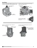
Page 16: ...naces Gas Control Knob ON OFF High Fire Adjusting Screw Overview of typical Two Stage Valve Used in eight stage and two stage furnaces Overview of typical Modulating Valve Used in 4 1 Electronic Modulation Low Fire and High Fire adjustments are made on printed circuit board behind removable cover Low Fire Adjusting Screw High Fire Adjusting Screw Terminal Block Gas Control Knob ON OFF Close up of ...

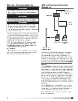
Page 17: ...dulating valve that causes the valve to send more or less gas to the furnace The combination valve is normally closed It requires 24 VAC to hold it open With 4 1 Turndown Electronic Modulation Start Up Furnaces all units After the gas piping has been installed and leak tested verify that all field installed components such as an air temperature sensor have been installed Verify that ON OFF gas cont...

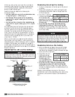
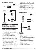
Page 18: ...mbination valve is set to the maximum setting Turn the regulator screw all the way in Modulating Valve High Fire Setting 1 Connect a manometer to the test port on the burner manifold 2 Press and hold button 1 until the LED lights solid red Release the button Observe the gas pressure on the manometer 3 Adjust the modulating valve by pushing button 1 to increase the pressure or by pushing button 2 t...

Page 19: ...ide of the gas valve Low fire gas pressure should be 0 875 in wg for natural gas or 2 5 in wg for LP gas 6 Return the A1092 Controller to normal operation by reconnecting the wire on the modulating valve and turning down the temperature selector 7 Shut down the furnace and then remove the manometer from the manifold and reinstall the plug in the test port 8 Return the furnace to normal operation Fu...

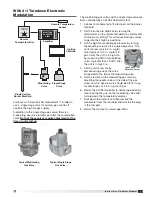
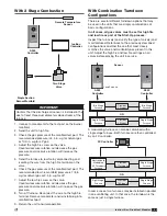
Page 20: ... manifold pressure must be checked and properly set on each manifold Two Stage Valve Two Stage Valve Split Burner Manifold Remote Temperature Sensor FX Controller Ignition Controller 8 Turn off furnace Reconnect the wire to the high fire terminal Remove manometer and reinstall plug into manifold test port 9 Connect manometer to the other manifold test port and repeat the high fire low fire set up seq...

Page 21: ...ge Valve Remote Temperature Sensor A350 Controller A350 JOHNSON CONTROLS Ignition Controller With 2 Stage Combustion With Combination Turndown Configurations There are several different turndown options that may be used in the units that are simply combinations of basic configurations In all cases all gas valves must be set for high fire and low fire as part of the Start Up process Inspect the furna...

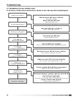
Page 22: ... Bleed gas line Supply gas pressure too high or too low Check that supply pressure is between 6 and 14 in wg for natural gas and between 11 and 14 in wg for LP gas Loose wire connections Check for tight wire connections No Spark a Spark electrode Ensure spark gap is 1 8 inch and ceramic insulator is not cracked Replace if necessary b Spark cable shorted to ground Replace spark cable c Ignition con...

Page 23: ...lay RH closed Heat relay RH is not energized Check for loose connections Repair or replace heat relay RH No Yes 24 VAC across W1 and L Heat switch S4 open or not wired Close or replace heat switch S4 No Yes 24 VAC across R and L Main disconnect DS1 open or defective Close repair or replace Main transformer TR1 fault Replace main transformer No Yes Continues on next page DT1 displayed on furnace co...

Page 24: ...pressure switch PS2 Combustion blower CM not functioning Replace fusing FU7 combustion blower or relay CM Yes No Ignition controller IC red LED blinks 1 time 2 times or 4 times Improper manifold pressure Set high and low manifold pressure refer to 4 1 Electronic Modulation Start Up section Faulty spark rod or spark gap does not equal 1 8 inch Replace spark rod or adjust gap to 1 8 inch Yes No cont...

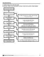
Page 25: ...nd C Main disconnect DS1 open or defective Close repair or replace Main transformer TR1 fault Replace main transformer No Yes Ignition controller IC red LED blinks 6 times Combustion blower CM not functioning Replace combustion blower or relay CM Air proving switch PS2 defective Replace air proving switch Yes No Ignition controller IC red LED blinks 1 time 2 times or 4 times Improper manifold pres...

Page 26: ...ss 22 and 21 Heat transformer TR2 fault Replace heating transformer No No Yes Yes N O contact on heat relay RH closed Heat relay RH is not energized Check for loose connections Repair of replace heat relay RH No Yes 24 VAC across W1 and C Heat switch S4 open or not wired Close or replace heat switch S4 No Yes 24 VAC across R and C Main disconnect DS1 open or defective Close repair or replace Main ...

Page 27: ...ive combustion blower CM No Yes No Ignition controller IC red LED blinks 1 time 2 times or 4 times No Cycle power to the unit and wait 30 seconds Everything is working properly consult factory Improper manifold pressure Set high and low manifold pressure refer to 8 Staged Start Up section Faulty spark rod or spark gap does not equal 1 8 inch Replace spark rod or adjust gap to 1 8 inch Yes Does the...

Page 28: ...s Yes 24 VAC across W1 and C Heat Switch S4 open Turn heat switch S4 on No Yes 24 VAC across R and C Main disconnect DS1 open or defective Close repair or replace Main transformer TR1 fault Replace main transformer No Yes Ignition controller IC red LED blinks 6 times Combustion blower CM not functioning Replace combustion blower or relay CR Air proving switch PS2 defective Replace air proving swit...

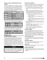
Page 29: ...e new setting and return to the Setpoints Menu press the Enter button To return to the Setpoints Menu without saving the change wait 15 seconds To exit Program Mode from the Setpoints Menu wait for 15 seconds Inlet Air Sensor iAS optional The Inlet Air Sensor monitors the temperature of the inlet air If the inlet air is above the setpoint the inlet air sensor shuts off the furnace and continues to...

Page 30: ...oints Menu and then scroll up or down until the display reads dtS Press the Enter button To edit the settings follow the instructions in Program Mode section Access the Inlet Air Sensor Go to the Setpoints Menu and then scroll up or down until the display reads iAS Press the Enter button Once the display reads iAS the display will change to the Inlet Air Sensor setting To edit the setting follow t...

Page 31: ...ean the ports with an aerosol degreaser or compressed air c Wipe the inside of the burner clean Cleaning the burner with a degreaser will slow the future buildup of dirt Before reinstalling the burner assembly look down the heat exchanger tubes to make sure they are clear of any debris Reinstall manifold and burner assembly reconnect wire leads and gas supply piping Turn on the electrical power an...

Page 32: ..._____________________ _________________________________________________ Date ___________________Time _____________ AM PM Notes ___________________________________________ _________________________________________________ _________________________________________________ _________________________________________________ _________________________________________________ Date ___________________Time ...

Reviews: