Indirect Gas-Fired Heat Modules
14
Connect the Supply Gas Line
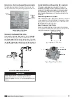
A manual shut off valve (gas cock), a 1/8 inch plugged
test port and a drip leg must be installed between the
gas supply pipe and the start of the gas train. The valve
and test port must be accessible for the connection of a
test gauge. Supply gas connections must be made by a
qualified installer and are not furnished by manufacturer.
Determine the Gas Supply Requirements
The data label located on the face of the furnace lists
the requirements for the gas being supplied to the unit.
Ground
Joint
Union
8 in. Trap
Gas to
Controls
From Gas Supply
Bleeder Valve or
1/8 in Plugged Tap
Gas Cock
Typical Gas Supply Piping Connection
Type of
Gas
Minimum
Gas
Supply
Pressure
Typical Furnace Data Label
each unit will be different
IMPORTANT
Before applying gas to the valves, test the gas
pressure to make sure it is less than 14 in. wg.
Pressures greater than 14 in. wg will damage the gas
valves.
Install Additional Regulator (if required)
If the gas supply pressure exceeds 14 in. wg, an
additional regulator must be installed to reduce the
pressure. The additional regulator is to be provided
and installed by others. The regulator must have a
listed leak limiting device or it must be vented to the
outdoors.
Test the System for Leaks
After installing the gas supply piping, perform a leak test
in accordance with the instructions in
Installation of Gas
Piping
in this manual. The leak test must be performed
before placing the unit in service.
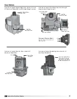
Gas Pressure Test Ports
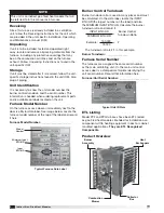
Burner manifolds and gas valves used in the furnaces
are supplied with test ports for temporary connection of
a pressure gauge or a magnehelic gauge.
Gas Supply In
Typical Split Burner Manifold
Test Ports
Typical Single Stage Gas Valve
Test Port
Test Port
ON / OFF
Gas Control Knob
®


