


31
PREPARE THE MODEL FOR FLIGHT
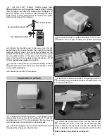
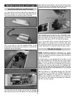
Install the Battery and Receiver
❏
1. Now that the tail covers have been completed, you
could do another C.G. check before determining where
the receiver battery and receiver will be mounted.
❏
2. If you wish to use the included battery mount,
assemble the mount and fi t your battery. Or, use your own
method to secure the battery.
❏
3. Securely glue the battery mount into the fuselage,
then mount your receiver and battery. 1/8" [3mm] double-
sided adhesive foam tape was used to mount the receiver
as shown, but fi rst the fuselage bottom was coated with
medium CA for better adhesion of the foam tape.
❏
4. Depending on the length of the ruddervator servo
wires and the location of your receiver, servo extensions
may be required. If using servo extensions, secure the
connection with pieces of 1/2" [13mm] shrink tubing.
❏
5. If you prefer not to connect and disconnect the
aileron servo wire directly into the receiver every time
you install and remove the wing, you may also connect
a servo extension to the aileron channel in your receiver.
Final C.G. Check
NOTE:
Additional information regarding C.G., lateral
balance and control throws is in the
Trimming Notes
section on page 34, but start by balancing your Quik-V6
as described below:
As stated earlier, a safe, beginning C.G. location is with
the Quik-V6 balanced 3" [76mm] aft of the wing leading
edge. The full C.G range is from 2-5/8" [67mm] to 3-1/4"
[83mm]. The Quik-V6 will fl y balanced beyond these
measurements, but for pylon racing you’ll probably fi nd
that you’ll settle right on 3" [76mm] or possibly 1/8" [3mm]
ahead of that (2-7/8" [73mm]) depending on your personal
taste and preferences.
With the Quik-V6 in a completely ready-to-fl y state (fuel
tank empty) with all components installed including the
propeller and propeller nut, use your C.G. Machine or
balance lines marked on the bottom of the wing to do
your fi nal C.G. check. Make any adjustments needed to
set the C.G. where desired.


