13
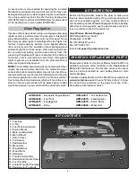
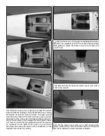
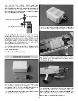
Z-bend). Be certain to remove any epoxy from the threads
on the pushrod wire. Allow the epoxy to harden.
❏
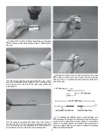
17. If you haven’t yet done so, make and test-fi t
the other pushrod the same way. After the epoxy has
hardened, thread the ball links onto the threaded end
of the pushrods. Set the pushrods aside until it’s time
to hinge the ruddervators. Skip to “Attach the V-tail” on
page 14.
Make the Wire Pushrods
❏
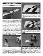
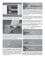
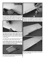
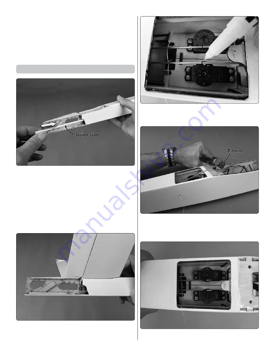
1. Cut the included pushrod guide tubes to a length
of 14-1/2" [370mm] and the included pushrod wires to a
length of 17-1/2" [445mm]. Use medium-grit sandpaper to
roughen the outside of the guide tubes so glue will adhere,
then install the tubes up through the formers in the fuselage.
❏
2. Thread a ball link ball about 3/8" [10mm] onto each
of the pushrod wires.
❏
3. Thoroughly clean the pushrod wires with a paper
towel square and denatured alcohol. Lightly coat the
wires with any light oil.
❏
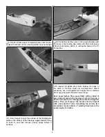
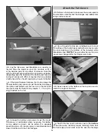
4. Install the pushrods up through the guide tubes.
Place the V-tail with the torque rods and ball link balls into
position and snap the ball links onto the balls.
❏
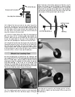
5. With the V-tail held in position and the ruddervators
and servo wheels
centered
, mark the pushrods where
they cross the holes in the servo wheels.
❏
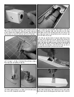
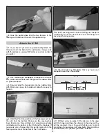
6. Disconnect the ball links from the metal balls. Cut
the pushrods 5/16" [8mm] past the marks, chamfer ends
of the wires to remove any burrs, and then make a Z-bend
in each pushrod wire at the marks.
❏
7. Connect the pushrods to the servos.


