11
Right Wing Servo
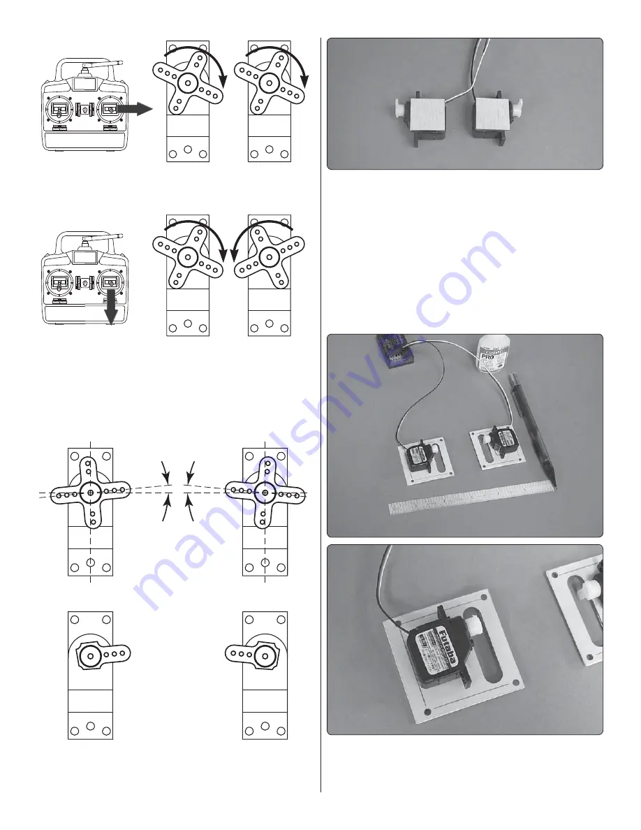
Right Aileron Control Input
Left Wing Servo
Right Wing Servo
“Up” Elevator Control Input
Left Wing Servo
❏
4. Make sure all the trims and sub trims are “zeroed” in
your transmitter. Program the mixing in your transmitter so the
servos respond in the correct direction as illustrated.
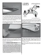
Cut off
the unused
arms
Right Wing Servo
Left Wing Servo
5°
5°
❏
5. Mount the servo arms to your servos so the inward-
opposing arms will have an approximately 5-degree angle
as shown. Cut off the unused arms.
❏
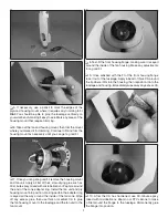
6. Cut the 1/32" x 3/4" x 1- 9/16" [1 x 20 x 40mm] balsa
sheet in half. Use medium-grit sandpaper to roughen the side
of each servo, then use medium CA to glue each balsa sheet
to the side of each servo.
Caution:
Do not use thin CA for
this step because it could wick into the servo through seams
in the case.
❏
7. Use a #53 (.046" [1.2mm]) drill to enlarge the holes in
your servo arms and the holes in the included control horns
to fi t the 1.2mm Z-bend pushrods. If you don’t have a drill you
can use a hobby blade, but do so carefully and don’t oversize
the holes or there will be free play in the linkages.
❏
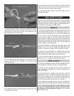
8. Use a straightedge and a pencil to mark lines on across
the inside of the hatch centered over the four screw holes. Glue
the servos to the hatches with medium CA, making sure the
servo doesn’t extend over any of the lines.


