14
❏
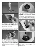
5. Use a piece of paper towel dampened with denatured
alcohol to wipe off the ink lines. Position the skid aligned over
the pin holes so none of them are visible. Then permanently
glue the skid to the wing with thin CA.
❏
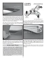
6. Fit, then glue on the other wing skid the same way.
Finish the Wings
❏
1. Fit, then use thin CA to glue the
alignment pegs
into
the root of both wings near the leading and trailing edge.
❏
2. Connect a servo wire extension to each aileron servo wire
coming out of the wing—just enough wire is needed so you
can reach the plugs through the canopy hatch for plugging into
your receiver—a total of 10" to 12" [255mm—300mm] of wire
is recommended with 10" [255mm] being the minimum, so
use whatever length extensions you need. For each Futaba
S3157 servo, a Futaba 75mm J-Series extension was used
(FUTM3909). Use tape or heat-shrink tubing to secure the
connection between the extension and the servo wire.
5-1/16" [129 mm]
5-1/16" [129 mm]
❏
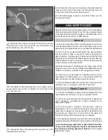
3.
Accurately
measure and mark the starting, recommended
C.G. location on the root rib of both wings 5-1/16" [129 mm]
back from the leading edge of each panel. Temporarily fi t
the wings together with the aluminum joiner tube, then use
a felt-tip pen and a straightedge to extend the lines partway
across the top of the wing as shown. (Don’t worry, the ink will
be wiped away later.)


