GRAUPNER GmbH & Co. KG D-73230 KIRCHHEIM/TECK GERMANY
Modifications reserved. No liability for printing errors Id. No. 0061845 04/2010
4
90°
The wings
... are built from parts (1 - 29), and are the most important components of our model.
Each wing consists of a centre section and a tip panel. The parts are assembled and
glued together over a flat building board. Start with the right-hand wing centre sec-
tion: cut out that part of the drawing and tape it down on the building board. Lay clear
greaseproof paper or plastic film over it to prevent parts sticking to the paper.
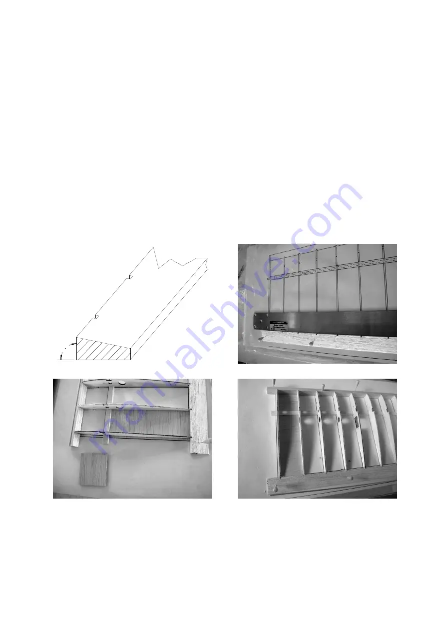
Pin down the leading edge (1), the trailing edge (2) and the main spar (3) over the
plan, checking that the distance between them matches the rib notches.
Caution:
the face which is at right-angles to the front edge is the underside
.
Tip:
fit two or
three ribs in the notches, position them carefully over the plan, then pin down the
spar, leading edge and trailing edge. Trim the bottom sheeting (12 and 13) to fit bet-
ween the leading edge, spar and trailing edge, and pin these parts to the building
board flush with the outside of the second rib (5). The remaining wing ribs (4 - 11)
can now be fitted and glued to the leading edge, spar, trailing edge and sheeting.
Caution: the ribs, leading edge, trailing edge, spar and sheeting must lie absolutely
flat on the building board. Take care to glue the first rib (4) in place exactly straight.
Glue the supplementary rib (5-z) in place, spaced 0.5 mm away from the rib (5) (tip:
fit or glue scrap 0.5 mm sheet between the parts as a spacer). Glue the secondary rib
(10-z) in place in the same way as the supplementary rib (5-z). Glue the top spar to
the structure, ensuring that it reaches the bottom of the notches in the laser-cut ribs.
Slide the joiner rube (15) into the appropriate hole; leave it projecting by about 5 - 6
mm. Cut the aluminium pivot tube (14) to length (approx. 400 mm) and slide it


