GRAUPNER GmbH & Co. KG D-73230 KIRCHHEIM/TECK GERMANY
Modifications reserved. No liability for printing errors Id. No. 0061845 04/2010
16
Tie the extension lead to the thread inside the wing (which you fitted before covering
the panel), and use it to pull the lead through to the wing root. Fit the servo in the
wing rib and secure it with the retaining screws supplied in the servo accessory pack.
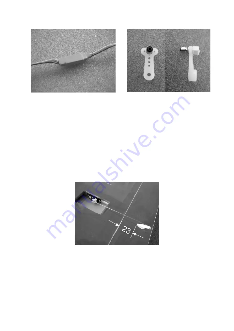
Slip the pushrod (86) through the swivel pushrod connector (77), set it at right-angles
to the wing trailing edge, and mark the point on the airbrake where the horn (87) is to
be fitted. Drill a 3 mm Ø hole at the marked point, and push the horn spigot into the
hole - note the orientation of the horn in the photo. Mark the outline of the horn base,
remove the film just inside the outline, and glue the horn (87) in the hole.
When the glue has set hard, connect the pushrod (86) to the airbrake horn (87), then
slip the plain end through the hole in the pushrod connector barrel. Switch the RC
system on, move the airbrake slider fully forward, and retract the airbrake. In this pos-
ition tighten the grubscrew in the swivel pushrod connector. Move the slider fully
back, and the airbrakes should extend fully. Snip off excess pushrod material, and
apply a drop of UHU thread-lock fluid to the grubscrew to prevent it working loose.
Cut the servo well cover (88) to size, and tape it to the wing; check that the pushrod
does not foul the inside of the cover at any point in its travel.
Canopy
The canopy (90) is held in place by the steel wire spring (91), which should be bent to
the shape shown in the drawing. Glue it to the canopy using Stabilit-Express; ensure
that both ends of the wire can be “sprung” in order to fit the canopy. The wire latch
should end flush with the canopy at the front end.


