7. SERVICING
7 .1 INTRODUCTION
The following paragraphs outline the various setvicing pro
cedures tor the Gr
a
ssoscrew Compressor Packages Series
GSLP.
Most of these procedures can be carried out on slte without
the necessity to remove neither the compressot nor the
electric motor trom the package base frame. Since the com
pressor - including slide valve actuator - is assembled with
only UNC-threaded beits and nuts. it is necessary to use
suitable tools. The
tact
is that all these beits are provided
with a decagonal (twe·Jve-sided) head (referred to in this ma
nual as �Ferry head screw"}, which means that box or ring
spanners have to be used instead of open end spanners.
For assistance with any detail of service or serv,cîng of an
item not covered by this manual, please consult Grasso.
7.2 GENERAL RECOMMENDATIONS
(o prevent needless downtime, have available on site all
parts that may be needed to carry out the repair before com
mencing any work.
To prevent dirt trom entering opened components. keep the
surrounds clean and cover the exposed werking areas with
plastic whenever possible.
Betere cleaning a component with a solvent to remove gum
or resîn like deposîts, remove all the 0-rings as they can be
chemîcally attacked. Alternatively check the compatibility of
the solvent with the 0-rings which are neoprene or Buna-N.
Unfortunately these solvents which most readily remove
carbon deposits (eg thrichlorethylene) rapidly attack both
neoprene and Buna-N. To ensure no traces of solvent will
be left to react with the oil and refrigerant. thoroughly dry
the component with an air blast. lmmediately clean every
entirely dismantled component, then check it roughly for
wear ot damage and oil the machined surfaces of bright
parts. Oiling these parts is particularly important when they
"!.re not reassembled until quite some time after. Otherwise
iey are sure to become rusty.
7.3 SHUTDOWN PROCEDURE
WARNING!
Before commencing
work
on any item on the package, en
sure
that the foflowing are carried out tor your own personal
protection.
a) Whenever the compressor is to be shut down for ser
vice, place warning tags on the electrical system and
the line valves. Others who do not know the machine
may be faulty or is being repaired must not attempt to
start the compressor until the servicing is complete
and it is ready for normal operation. Exposed electric
wiring must always carry a warning tag even though it
is disconnected from thè power-
si:;ppfy_
b) Stop the compressor with the stop button on the con
trol cabine!.
1
Oisconnect the starter frorn the power supply.
-
d) Disconnect the control cabine! from the power supply
.
GRBSSï:i
ROlf"HCSVOORSO<RFî'9ETRIEBSAJll.flfllli<'
"'51RUCTIOll"""'.....,_i.a.171NSTRUCTION
e) Close compressor suction stop valve and discharge
stop valve.
f} lf the compressor is fltted with an economizer port, close
the eoonomizer stop valve.
g) Relieve the gas pressure in the package by opening
the pressure safety valve on the oil separator to either
a pump out compressor or to atmosphere. lf using a
pump out compressor, pull the package pressure to
atmospheric pressure [1 bar(a) on the suction press
ure gauge] and open the pressure safety valve on the
separator to atmosphere.
h) Leave the pressure safety valve open to the atrnos-
phere all the time while werking on the compressor.
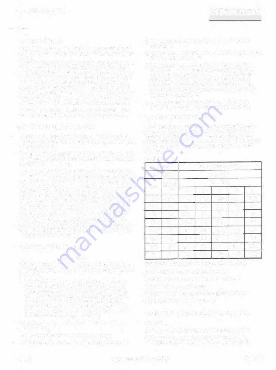
7 .4 BOLT TIGHTENING TORQUES
The tighteoing torques tor servicing the vanovs beits and
screws used ,n the oompressor are given ïn tab Ie 7 .1- All
fas1eners (eg. the Ferry head screws) used in the com
pressor unit, are high lensile Grade 8 only and they must al
ways be torqued to condition B when the compressor is
serviced.
TABLE7.1
Fastener
Tighteningtorques in N.m
Dia
Pitch
Grade0••
Thread
•condition
inch
inch
A
B
C
D
E
1/4
20
16.3
12.2
10_8
8.1
14.9
5/16
18
34
24
23
16.9
31
3/8
16
61
47
42
31
54
1/2
13
149
108
100
75
134
5/8
11
298
230
199
149
268
3/4
10
515
380
346
258
464
7/8
9
813
624
545
407
732
1
8
1220
922
818
610
1098
TIGHTENING TOROUES FOR THREADED BOL TS
A) Non-lub(icated solvent-cleaned and dry
B) Lubricated with rust preventative or z,nc pla1ed
C) Lubricated with oil or grease
D) Lubricated with dry lube film or graphite/oil mixture
E) Lubricated with loctite or sealants
7 .5
SHAFT SEAL
REPLACEMENT (refer to fig.
7.1)
REMOVAL
a) Carry out the shutdown procedure in paragraph 7 .3.
b) Remo\le the coupling guard, coupling spacer and
coupling flange with key trom the compressor shaft.
92.01
Compressor Package GSLP
Page7.1


