background image

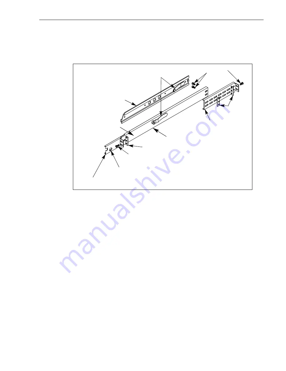
Rack mount hardware shipped with the Profile XP system

23 July 2004

Profile XP System Guide

333

Rack mount hardware shipped with the Profile XP system

Your Profile XP comes with rack mounting hardware as shown. The Profile XP and 
PAC216 are shipped with the chassis sections already attached.

Rack mounting Fibre Channel RAID systems

To rack mount these storage systems, refer to the rack mounting information in the 
PFC500, PFR 500, or PFR600 Instruction Manuals.

Chassis section pre-installed

Automatic

Rack

Section

10-32 PHS

10-32 PHS

Flat

Nut

Flat Nut Bar

Intermediate

Stop Latch

Rear

NOTE: Right-hand and left-hand stationary section is designated by the 
RH and the LH marked on the rails. Stop latch holes should be towards 

Stationary

Summary of Contents for PROFILE XP PVS Series

Page 1: ...Profile XP PVS SERIES MEDIA PLATFORMS System Guide SOFTWARE VERSION 5 4 071 8289 01 JULY 2004 the most watched worldwide ...

Page 2: ...rrors or inaccuracies that may appear in this publication U S Government Restricted Rights Legend Use duplication or disclosure by the United States Government is subject to restrictions as set forth in subparagraph c 1 ii of the Rights in Technical Data and Computer Software clause at DFARS 252 277 7013 or in subparagraph c 1 and 2 of the Commercial Computer Software Restricted Rights clause at F...

Page 3: ...r Ethernet IP Video Networks 28 Front panel controls and indicators 29 Rear Panel View 32 Standard accessories 33 Profile XP Media Platform system overview 34 High level block diagram 34 Board level block diagram 35 Starting the Profile XP system 43 Logging on Windows NT 44 Automatic Logon 44 Logging on as Administrator 44 Logging on as Profile 45 Shutting down the Profile XP system 46 Chapter 2 W...

Page 4: ...esetting the PFC500 system clock 117 Chapter 4 Adding or Removing Channels Using the Channel Configuration dialog box 119 Displaying the Channel Configuration dialog box 120 Working with channels 121 Default settings for channels you add 121 Why resources appear dimmed red or in use 122 Using Tool Tips to manage resources 123 Using the Warning symbol to find shared resources 124 Using the Summary ...

Page 5: ... Monitor output 185 Enabling or disabling NTSC pedestal 186 Configuring Text Overlay on the Video Monitor output 187 Enabling Video Monitor timecode burn in 188 Using multiple video tracks for one channel 190 Chapter 6 Modifying a Channel Audio Settings About Profile XP Audio 193 Determining the number of audio channels available 193 Determining the audio formats available 194 Adding or removing a...

Page 6: ...S 422 remote control in VdrPanel 248 Setting up RS 422 remote control using Prolink 251 How to set up Prolink 251 Overview of the Prolink communications window 252 Running PortServer to enable remote operation 253 Setting up AMP remote control 254 Configuring AMP protocol control 254 Using the AMP application for local control 256 Setting Options 257 Loading a clip 258 Playing a clip 258 Recording...

Page 7: ...annel Video network 301 Common Ethernet video network problems 305 Testing the Ethernet Video network 306 Appendix A Electrical and Environmental Specifications General Information 311 Test Equipment 311 Electrical Specifications 312 Profile XP System Power Specifications 317 PAC 216 Power Requirements 317 Environmental Criteria 318 Appendix B Connector Pin outs S VGA connector 319 RJ 45 Ethernet ...

Page 8: ...is 338 XLR216 and BNC216 AES EBU Breakout Panels 338 PAC216 Profile Audio Chassis 339 I O Panel 339 PFC500 Fibre Channel RAID Chassis 340 PFC500E Expansion Chassis 340 PFR500 Fibre Channel RAID Chassis 341 PFR500E Expansion Chassis 341 PFR600 Fibre Channel RAID Chassis 342 PFR600E Expansion Chassis 342 PFR700 Fibre Channel RAID Chassis 343 PFR700E Expansion Chassis 343 Index ...

Page 9: ...s Grass Valley Group P r o f i l e X P M a n u a l F a m il y o f X P S e r ie s G r a s s V a l l e y G r o u p Release Notes Path for the Installer Path for the Operator System Guide User Manuals Other Manuals Contains the latest information about Profile XP hardware and software shipped with your system P r o f i l e X P M a n u a l F a m il y o f X P S e r ie s G r a s s V a l l e y G r o u p ...

Page 10: ...tion for using NetCentral to monitor various types of broadcast equipment including Profile XP systems from a central monitoring station Profile XP Release Notes Contains the latest information about the Profile hardware and the software release shipped on your system This information includes software specifications and requirements feature changes from the previous releases helpful system admini...

Page 11: ...ls Describes the basics of adding configuring or removing channels Information on advanced channel settings are referenced to chapters 5 through 7 Chapter 5 Modifying a Channel Video Settings Describes how to modify the video settings for a channel Chapter 6 Modifying a Channel Audio Settings Describes how to modify the audio settings for a channel Chapter 7 Modifying a Channel Timecode Settings D...

Page 12: ...hese as additional sources for information On line manuals Electronic versions of the following manuals are located on the system drive of your Profile XP Media Platform and on the Profile XP software CD ROM Installation Guide for your model Profile XP System Guide Profile XP User Manual Profile XP Release Notes Profile XP Service Manual NetCentral User Guide PFC 500 Instruction Manual PFR 500 Ins...

Page 13: ...t representative may be available in your country To locate the support representative for your country visit the product support Web page on the Grass Valley Web site Profile Users Group You can connect with other Profile XP Media Platform users to ask questions or share advice tips and hints Send e mail to profile users thomson net to join the community and benefit from the experience of others ...

Page 14: ...Preface 14 Profile XP System Guide 23 July 2004 ...

Page 15: ...ounded through the grounding conductor of the power cord To avoid electric shock the grounding conductor must be connected to earth ground Before making connections to the input or output terminals of the product ensure that the product is properly grounded Do Not Operate Without Covers To avoid electric shock or fire hazard do not operate this product with covers or panels removed Do Not operate ...

Page 16: ...ard manufacturer s instructions Safety Terms and Symbols Terms in This Manual These terms may appear in this manual WARNING Warning statements identify conditions or practices that can result in personal injury or loss of life CAUTION Caution statements identify conditions or practices that can result in damage to the equipment or other property Terms on the Product These terms may appear on the p...

Page 17: ...n radiate radio frequency energy and if not installed and used in accordance with the instruction manual may cause harmful interference to radio communications Operation of this equipment in a residential area is likely to cause harmful interference in which case the user will be required to correct the interference at his own expense Changes or modifications not expressly approved by Thomson Broa...

Page 18: ...egulation CFR Title 21 Subchapter J The International Electrotechnical Commission IEC Standard 825 Radiation of Laser Products Equipment Classification Requirements and User s Guide governs laser products outside the United States Europe and member nations of the European Free Trade Association fall under the jurisdiction of the Comité Européen de Normalization Electrotechnique CENELEC FCC Emissio...

Page 19: ...e a DVCPRO 50 can immediately follow an MPEG 2 clip at 12 Mb s on any playout channel The only limitation is that you cannot create or play master clips complex movies that include more than one compression type The PVS3000 Series combines both standard and high definition capabilities in a single Profile XP Media Platform You can record and play SD clips in all the PVS1100 supported formats on yo...

Page 20: ...h definition can record ancillary data When you play these clips the ancillary data is inserted on the specified lines If your chosen output does not support as much ancillary data as was recorded on each line the data is truncated at the maximum for that output This occurs for example when you play HD clips on an SD output ...

Page 21: ...rking up to 30 Mb s Remote control including Remote Applications over Ethernet RS 422 control protocol including AMP VDCP Odetics BVW or Profile protocols GPI Trigger 8 I O PVS1000 features include Up to 8 standard definition SD channels of broadcast quality video MPEG 2 4 2 2 Main Level from 4 50 Mb s long GoP for SD SMPTE 259M 270MB Serial Digital I O Analog monitor optional 525 60 or 625 50 ope...

Page 22: ...t 30 40 or 50 Mb s CBG requires 50 Mb s option Back to back playout of all formats on any codec SDTI optional two channels each configurable as input or output DVCPRO 25 input at 1x 2x 4x output at 1x 4x DVCPRO 50 input at 1x 2x output at 1x New real time processor board with improved processing capacity provides greater bandwidth for fibre channel transfers concurrent channel operations etc 525 6...

Page 23: ...og monitor with text overlay and timecode burn in Up conversion of MPEG 2 4 2 0 clips with aspect ratio configuration requires Definition Independent option 1080i and 720p line rates for HD 50 59 94 and 60 fps accepts house black and tri level sync reference PVS2000 Series channel configurations by model Model Number Number of HD Encoder Boards Number of HD Decoder Boards Channel Configuration PVS...

Page 24: ...vel from 4 to 15 Mb s long GoP for SD MPEG 2 4 2 2 Main Level from 4 25 Mb s long GoP or up to 50 Mb s with 50 Mb s option for SD MPEG D10 I frame at 30 40 or 50 Mb s CBG with 50 Mb s option for SD Back to back playout of all SD formats on any SD codec Up conversion of SD MPEG 2 4 2 0 clips with aspect ratio configuration requires Definition Independent option Agile Output Down conversion of HD cl...

Page 25: ...g GoP or up to 50 Mb s with 50 Mb s option for SD MPEG D10 I frame at 30 40 or 50 Mb s CBG with 50 Mb s option for SD Back to back playout of all SD formats on any SD codec Up conversion of SD MPEG 2 4 2 0 clips with aspect ratio configuration Down conversion of HD clips with aspect ratio configuration PVS3500 Series channel configurations by model Model Number Number of SD video codecs Number of ...

Page 26: ...ide to modify default channel settings to satisfy the needs of your system For more information about channels refer to Chapter 4 Adding or Removing Channels Default channel type Video I O connections Audio connectionsa a The number of audio I Os is determined by your Profile XP model and the number of Audio boards installed For SDTI audio is part of the data stream Timecode I O Recorder 1 SDI or ...

Page 27: ...he advantages of long GoP encoding without the limitations The PVS1100 provides MPEG 2 4 2 2 support at bit rates up to 25 Mb s and up to 50 Mb s with the 50 Mb s option The PVS1100 also provides MPEG D10 compatibility MPEG D10 is an MPEG format that was developed for tape It is characterized by a selectable fixed bit rate 30 40 or 50 Mb s and constrained byte GoP CBG that prevents the size of a f...

Page 28: ...entralized Storage The Profile XP centralized storage solution the Open SAN is implemented using a Fibre Channel switch fabric to connect all RAID storage chassis and Profile XP Media Platforms Centralized storage provides multiple Profile XP Media Platforms simultaneous access to a common pool of media As in distributed storage a redundant Fibre Channel connection option is available to provide a...

Page 29: ...ower On LED indicates the standby switch is in the on position and that secondary voltages are present in the chassis Standby Switch provides system On Off control System Fault LED indicates a system fault exist somewhere in the Profile XP unit 0624 5 Standby On Switch 2 System Fault LED 3 Chassis Pull Standby On LED Pull here to open each side Accessory Door Accessory Door 1 ...

Page 30: ...on the standard Profile XP system System Disk contains the Windows NT operating system and Profile XP system software and applications 1 44MB Floppy Disk Drive CD ROM Drive for maintaining the Windows NT operating system and performing Profile XP system software upgrades NOTE If an accessory door is accidentally dislocated from its hinges you can easily pop it back into place 0624 4 3 CD ROM Drive...

Page 31: ...of the mirroring system as follows Green Drives are in Mirror mode Red Drives in Single mode Orange Drive activity The Buzzer Off switch can be used to silence the buzzer which sounds under the following conditions Short beep during power on indicates successful boot up Second beep indicates the mirroring system is running in single mode Continuous or intermittent beep to indicate a drive failure ...

Page 32: ...d in Appendix C Rack Mounting Information and Rear Panel Drawings 8112 1 Profile XP Media Platform Video I O VideoOut or Video Monitor LTC GPI Video network opt FC Disk Port A FC Disk Port B Audio Channels 1 16 opt SDTI opt Audio Channels 1 16 Optional Power Supply Power Cord Power Good LED Reference In Loop Thru RS 422 Breakout Mouse Keyboard Com1 RS 232 Monitor Parallel Port Ethernet Windows NT ...

Page 33: ...nuals Include Installation Guide Profile XP System Guide Profile XP User Manual Profile XP Service Manual Profile XP Release Notes Software package which includes the Profile XP Software CD ROM Windows NT software package Keyboard and mouse I O Panel and cables provides LTC RS 422 GPI interfaces Power cable Rack mounting slides Ethernet cable System rebuild CD ROM ...

Page 34: ...Subsystem provides a platform for running Windows based applications for configuring and controlling the Real Time Subsystem both locally and remotely Real Time Subsystem The Real Time Subsystem contains a real time processor and peripheral devices and runs the VXWorks operating system The Real Time Subsystem manages all the hardware involved in controlling the flow of video audio timecode in and ...

Page 35: ...erations by sending SCSI protocol commands over one or more Fibre Channel links Platform Resources The platform resources provide the infrastructure necessary to operate interconnect and integrate all the Application Subsystem Real Time Subsystem components The elements that comprise the Platform Resources are Multi slot PCI bus video audio crosspoint fabric power supply and system cooling Board l...

Page 36: ...tem Port A Port B SDI 4Out Audio Ch1 16 Audio Ch1 16 Audio Interface Audio Interface Ethernet Video Network Real Time System Board Net Fibre Ch Video Network Video Monitor NTSC PAL PCI Bus 8 CH RS 422 Interface Real Time Processor PCI B us 8112 3 I O Panel Fibre Channel Disk Interface Applications Processor plus Windows NT 3 5 FD CD HD Mirror HD Add Encoder Decoder Boards PCI B us LTC GPI I Os Gen...

Page 37: ...thernet Video Network Net Fibre Ch Video Network Media Storage Subsystem Port A Port B Fibre Channel Disk Interface PFC 500 System RAID 3 Storage PCI Bus HD in HD out SD SDI NTSC PAL 8 CH RS 422 Interface Real Time Processor PCI Bus 0624 65 LTC GPI Ref In 4 4 I O Panel Applications Processor plus Windows NT 3 5 FD CD HD Mirror HD 8 8 Add Encoder Decoder Boards PCI Bus LTC GPI I Os Genlock Video Em...

Page 38: ... A Port B SDI 4Out Audio Ch1 16 Audio Ch1 16 Audio Interface Audio Interface Ethernet Video Network Real Time System Board Net Fibre Ch Video Network Video Monitor NTSC PAL PCI Bus 8 CH RS 422 Interface Real Time Processor SDTI 2In 2Out PCI Bus 8112 4 LTC GPI Ref In 4 4 I O Panel Fibre Channel Disk Interface Applications Processor plus Windows NT 3 5 FD CD HD Mirror HD 8 8 Add Processor Boards PCI...

Page 39: ...Application Processor Board The Application Engine is a standard NLX single board computer The Application Subsystem provides a platform for running Windows based applications for configuring and controlling the Real Time Subsystem both locally and remotely Rear panel I O includes Mouse Keyboard and SVGA Connectors One Serial Port One Parallel Port Two USB Ports Audio Line Level IN OUT and Mic Inp...

Page 40: ...0 Mb s SMPTE 259M either 2In 2Out or 4 Out through four BNC connectors on the rear of the board An internal frame buffer is provided for each video input on the board for auto timing synchronous and asynchronous inputs Embedded audio is supported maximum of 8 channels audio per video input and is routed over the video routing fabric VITC can be read from each input and generated on each output Hig...

Page 41: ...des 2 channels of video processing Encoding bit rates are from 4 Mb s to 50 Mb s Up to four of these type boards can be installed in a Profile XP system For record mode video is routed from the Video I O boards over the video transport fabric to the MPEG 2 Encoder Board MPEG 2 compressed data is moved over the PCI bus to the Media Storage Subsystem For play mode MPEG 2 compressed data is routed fr...

Page 42: ...udes the following components Fibre Channel Disk Board This is a dual port Fibre Channel Disk board for connecting the Profile XP system to the external Fibre Channel RAID storage system in either a local or centralized storage configuration In local storage configurations the Fibre Channel RAID storage system is connected directly to the Fibre Channel Disk board In centralized storage configurati...

Page 43: ...rpret other disk access LED or status LED behavior PFR600 RAID Storage systems Wait until all disk access LEDs are steady green is illuminated approximately 4 minutes The rear panel 7 segment LED displays the chassis address Refer to the PFR 600 Instruction Manual to interpret other disk access LED or 7 segment LED behavior PFR500 RAID Storage systems Wait until all disk access LEDs are steady gre...

Page 44: ...When the Profile XP system is powered On you may interrupt automatic logon and logon as Administrator It is not necessary to logon as administrator to configure Profile System software However you must logon as Administrator for Windows NT administration and to Configure Ethernet network settings see Chapter 11 Setting up a Simple Network Install new software applications or upgrades see Profile X...

Page 45: ...hen the Begin Logon dialog box appears release the Shift key then press the Control Alt Del key sequence e Enter the following then click OK Username Administrator Password triton You are now logged on as Administrator and can modify system settings Logging on as Profile After performing system administrative tasks using the Administrator user account Profile account to enable the automatic logon ...

Page 46: ...itch to Standby IMPORTANT If your Profile XP Media Platform is part of an Open SAN disregard the following step and refer to the instructions Open SAN Instruction Manual for shutting down the Open SAN 5 Power off the RAID storage system by powering off the RAID Controller chassis prior to or at the same time as the RAID Expansion chassis CAUTION You must always power off the PFR500 RAID Controller...

Page 47: ...y channels and configure system hardware settings Some models allow you to configure codecs The Configuration Manager window appears as shown here This chapter gives a brief tour of Configuration Manager Also included are instructions for remote configuration and saving restoring configuration settings Sections in this chapter include Tour of Configuration Manager Viewing board location informatio...

Page 48: ...tput settings and on the models that have them video codecs Audio setup items used to configure audio input and output settings Channel Configuration used to add and modify channels File System Choosing File System in Configuration Manager opens the Disk Utility dialog box Use the pages in the Disk Utility to configure local storage connected directly to the Profile XP system IMPORTANT If your Pro...

Page 49: ...oosing Network in Configuration Manager opens the video network configuration pages Use these pages to configure the settings for the optional video network For more information on setting up the video network option see Chapter 11 Setting up a Simple Network ...

Page 50: ...buffer operation input blanking loss of signal behavior and VITC reader settings Video Output used to configure the settings for each video output including loss of signal behavior vertical interval blanking and VITC generator settings Video Codec Used to configure the operation of each video codec present on the Profile XP models that have one or more Video Codec boards Video Monitor used to set ...

Page 51: ...l The audio reference level is used to set the default audio level in some Profile applications Audio Input used to adjust the analog audio input gain and monitor the status of AES EBU input signals Audio Output used to adjust the analog audio output gain Audio Routing used to set up audio sources and destinations for Profile XP audio channels See Chapter 6 Modifying a Channel Audio Settings for m...

Page 52: ...guration in Configuration Manager opens the SabreTooth License Request wizard The SabreTooth License Manager is used to obtain install and manage licenses required to enable some of the optional features of your Profile XP Media Platform See Chapter 9 Managing Optional Licenses for more information on using Channel Configuration ...

Page 53: ...Choosing Channel Configuration in Configuration Manager opens the Channel Configuration window Channel Configuration is used to modify or create channels that are used by Profile applications See Chapter 4 Adding or Removing Channels for more information on using Channel Configuration ...

Page 54: ...ware settings in Configuration Manager Summary dialog boxes are displayed when you click the Finish button on a configuration page The Video Monitor Summary dialog box is shown here as an example Clicking Back in a summary dialog box returns you to the configuration page without saving your settings Clicking the OK closes the summary dialog box and saves your settings ...

Page 55: ... or hide summary dialog boxes You can choose to hide the summary dialog boxes This allows you to click the Finish button on configuration pages to store your settings without displaying the summary To show or hide summary dialog boxes in the Configuration Manager View menu choose Show Summary ...

Page 56: ... board location information Selecting Board Location in the View menu allows you to view the location and type of circuit boards installed in your Profile XP To view board location information 1 Select View Board Location The Profile Board Location window appears 2 Click Ok to close the window ...

Page 57: ... configuration file You can choose to save the current channel and hardware settings or just channel settings by saving the appropriate file type To save a copy of your system configuration 1 In Configuration Manager select File Save a Copy The Save As dialog box appears 2 Choose whether to save hardware and channel configuration cfg or the channel configuration only cdf using the Save as type dro...

Page 58: ... 1 In Configuration Manager select File Open The Open dialog box appears 2 Choose the file type you want to open either cdf or cfg using the File of type drop down list Opening a cdf file changes the channel configuration settings and keeps the existing hardware settings Opening a cfg file changes both channel and hardware settings 3 Find and select the file name you want to open then click Open A...

Page 59: ...u if you want to save the current configuration before using Import When you import a configuration you can select whether you want to modify hardware settings channel configuration or both Channel configurations are used by applications and specify what video audio and timecode resources makeup each channel The hardware settings specify the video and audio hardware setup for the Profile XP system...

Page 60: ...Chapter 2 Working with Configuration Manager 60 Profile XP System Guide 23 July 2004 Importing a configuration To import a configuration 1 In Configuration Manager choose File Import ...

Page 61: ... dialog box select the Profile XP system from which you want to import the configuration 3 In the Components drop down list select whether you want to import hardware or channel configuration or both then click the Import button The remote configuration is imported to the local Profile XP system ...

Page 62: ...rofile software on an Windows NT workstation To configure remote Profile XP systems 1 Set up the Windows NT Ethernet network using the procedures in Chapter 11 Setting up a Simple Network then return to this procedure 2 Install Profile system software on the Windows NT workstation you want to use to monitor and configure remote Profile XP systems 3 Start Port Server on all Profile XP systems by do...

Page 63: ...mote Connection dialog box appears 5 Select a Profile XP system in the Remote Host List then click Connect The Configuration Manager reappears Note that the remote host now appears in the Configuration Manager title bar 6 Configure the remote machine using Configuration Manager Then use step 4 and step 5 to configure other remote Profile XP systems as required Remote Host Name ...

Page 64: ...Chapter 2 Working with Configuration Manager 64 Profile XP System Guide 23 July 2004 ...

Page 65: ...e procedures for configuring and maintaining the RAID storage systems using GVG Disk Utility Topics included are RAID chassis product descriptions on page 66 Estimating storage capacity on page 69 Determining maximum video data rate per channel on page 70 Connecting RAID chassis cabling on page 70 Configuring RAID storage using GVG Disk Utility on page 71 Performing RAID storage maintenance using ...

Page 66: ...ant RAID controllers for automatic failover Failover can occur when the primary RAID Controller Fibre Channel Port of the Profile XP or Fibre Channel cable fails When failover occurs the system continues to run with minimal interruption For servicing information on the PFC500 RAID storage system including monitoring the front and rear panel LED indicators and replacing serviceable modules refer to...

Page 67: ...46 TB depending on disk drive option The PFR600E RAID Expansion Chassis provides additional storage capacity It is an identical chassis with two Loop Bypass Board installed Up to five PFR600E RAID Expansion Chassis can be connected to a single PFR600 comprising a single disk array storage system with a total of 60 drives and 3 6 TB 7 3 TB or 14 6 TB of storage depending on disk drive option The bu...

Page 68: ...e is no drive 15 between the PFR700 RAID Chassis and the PFR 700E RAID Expansion Chassis The PFR700 utilizes dual FC AL technology allowing two loop configurations within a single chassis Loop integrity is maintained during failures without user intervention Each loop and associated circuits along with all other active components are on redundant separate hot swappable modules This improves servic...

Page 69: ...ge capacity estimates in hours using 73 GB drives Video Data Rate 5 Drives 10 Drives 15 Drives 20 Drives 25 Drives 30 Drives 4 Mb s 37 8 75 6 113 4 151 2 189 226 8 8 Mb s 25 4 50 8 76 2 101 6 127 152 4 12 Mb s 19 1 38 2 57 3 76 4 95 5 114 6 15 Mb s 16 1 32 2 48 3 64 4 80 5 96 6 18 Mb s 13 8 27 6 41 4 55 2 69 82 8 24 Mb s 10 8 21 6 32 4 43 2 54 64 8 32 Mb s 8 4 16 8 25 2 33 6 42 50 4 40 Mb s 6 8 13...

Page 70: ...gh playout and recording take priority over other operations exceeding your Profile XP system bandwidth may result in record or playback problems If you are unsure about maximum video data rate per channel or your Profile XP available system bandwidth consult your Grass Valley support representative Be prepared to supply the number of video channels the usual bit rate uncompressed VBI usage the nu...

Page 71: ...ognizable by the Profile XP Media Platform This section includes the following About configuring storage on page 72 Introducing the GVG Disk Utility on page 75 Binding disks and creating a video file system on page 77 Configuring hot spare drives on page 83 Changing the video file system volume name on page 85 Expanding storage on page 87 Unbinding LUNs for reconfiguration on page 91 NOTE If your ...

Page 72: ...s 0 4 and 5 9 must be bound as two different LUNs To help in finding the physical location of disks in large systems the disk utility includes an Identify Disk button which allows the selected disk drive s disk access light to flash After binding disk modules become slot specific and cannot be moved to other disk module slots Unbinding disk modules Unbinding reverses the bind process Unbinding mig...

Page 73: ... party Profile XP control software which requires a specific volume name Using Hot Spare drives You can bind disks as hot spare drives Hot spare drives are on standby and are used in the event of a drive failure in a data LUN If a drive fails the RAID Controller automatically selects a hot spare drive to use in place of the failed drive This prevents the system from operating in a degraded state e...

Page 74: ... designate as hot spares are bound as part of a data LUN you must unbind the drives first then bind them as hot spares Refer to Unbinding LUNs for reconfiguration on page 91 You can configure any disk in the array as a hot spare drive however hot spare drives are available only to RAID Controller to which they are connected ...

Page 75: ... Model Provides a logical grouping of RAID chassis models i e all PFR500 RAID Controller Chassis connected are listed under the PFR500 icon Controller Represents the RAID Controllers found These are numbered in the order discovered The controller icon represents both RAID Controller A and if installed RAID Controller B To determine if an optional RAID Controller B is installed select the Controlle...

Page 76: ...oftware is available to monitor your Profile XP media platform and the attached RAID storage system however some limited status information for storage subsystems is displayed in the GVG Disk Utility This can be helpful when configuring storage You can view status information by selecting these items in the tree view Storage Model Controller Bound LUN Disk ...

Page 77: ...NOTE Make sure you allow adequate time for binding disk modules into LUNs PFR500 and PFR600 controllers bind each LUN in turn but take less than a minute for each LUN PFC500 and PFR700 controllers bind multiple LUNs at the same time yet take more than an hour to bind a LUN Large drive capacities and multiple LUNs can increase the binding time to 10 hours or more NOTE If you want to use hot spare d...

Page 78: ... set the Fibre Channel ID otherwise proceed to step 4 a Expand the tree view and right click the Controller0 icon under PFR500 or PFR600 then select Set Fibre Channel ID in the context menu b In the Set Fibre Channel ID dialog box enter IDs as shown then click OK c Click OK in the Operation Successful dialog box d Reboot the PFR500 or PFR600 RAID storage system and the Profile XP media platform us...

Page 79: ...ick the Unbound node for a controller then select Bind LUNs in the context menu Peer controllers that share the same set of disks are automatically selected as a pair The Binding LUN dialog box opens showing all unbound disks for the controller listed in the Available Disk list b Select RAID 3 using the LUN TYPE drop down box c Select five contiguous disks then click the add button to add them to ...

Page 80: ...PFR700 controllers take more than an hour to bind a LUN but allow multiple binding processes at the same time f Upon 100 completion click Close in Progress Report window Do not proceed until all LUNs are finished binding g Restart the Windows operating system on the Profile XP Media Platform h Start Configuration Manager using the desktop shortcut or by selecting Start Programs Profile Application...

Page 81: ...P System Guide 81 7 Enter a volume name or accept the default name then click Next 8 Select Yes create a file system using all RAID3 LUNs then click Finish 9 Click OK in the warning message box The Progress Report window appears showing the create file system task status ...

Page 82: ...RAID Storage Using GVG Disk Utility 82 Profile XP System Guide 23 July 2004 10 When the reboot message appears click OK to restart the Profile XP Media Platform Afterward the storage system is ready for record play operation ...

Page 83: ...them as hot spares Refer to Unbinding LUNs for reconfiguration on page 91 To bind drives as hot spare drives 1 Start Configuration Manager using the desktop shortcut or by selecting Start Programs Profile Applications Configuration Manager 2 In Configuration Manager click File System in the Configuration Manager window The GVG Disk Utility appears 3 To bind unbound disks as hot spares right click ...

Page 84: ...tton to add them to the Selected Disks list NOTE As an aid in identifying a disk module s physical location select it in the Selected Disks list then click Identify Disks This causes the disk drive LED to flash 6 Click OK to close the Binding LUN dialog box and begin the binding process The Progress Report dialog box opens showing the status of the binding process 7 Repeat step 3 through step 6 to...

Page 85: ...the video file system volume name at any time without affecting the media files stored on the system Changing the volume name may be required with some third party Profile XP control software which requires a specific volume name To change the file system volume name 1 Start Configuration Manager using the desktop shortcut or by selecting Start Programs Profile Applications Configuration Manager 2...

Page 86: ...a new volume name then click Next 5 Select No set the volume name only then click Finish The Progress Report window appears showing the change volume name task status 6 Upon 100 completion click Close in Progress Report window Be sure to restart applications that access disk storage on the Profile XP system ...

Page 87: ...le XP Media Platform to make hardware connections then return to this procedure to configure the storage system To create a video file system on expanded storage 1 Start Configuration Manager using the desktop shortcut or by selecting Start Programs Profile Applications Configuration Manager 2 In Configuration Manager click File System to start GVG Disk Utility 3 Expand the tree view and identify ...

Page 88: ...ion select it in the Selected Disks list then click Identify Disks This causes the disk drive LED to flash d Click OK to close the Binding LUN dialog box and begin the binding process The Progress Report dialog box opens showing the status of the binding process e Repeat step a through step d for all unbound disks on all remaining controllers displayed in the tree view NOTE PFR500 and PFR600 contr...

Page 89: ... Restart the Windows operating system on the Profile XP Media Platform h Start Configuration Manager using the desktop shortcut or by selecting Start Programs Profile Applications Configuration Manager i In Configuration Manager click File System to start the GVG Disk Utility 5 In the GVG Disk Utility main menu click Tools Make File System The File System wizard appears ...

Page 90: ...stem Guide 23 July 2004 6 Enter a volume name or accept the default name then click Next 7 Select Yes create a file system using all RAID3 LUNs then click Finish 8 Click OK in the warning message box The Progress Report window appears showing the create file system task status ...

Page 91: ... a PFR500 or PFR600 RAID Controller Chassis always use the GVG Disk Utility to unbind the disk modules in the expansion chassis before disconnecting them from the original RAID Controller chassis CAUTION Unbinding destroys all user media files stored on the disk modules This section includes the following procedures Unbinding LUNs PFC500 and PFR700 Storage Systems Unbinding LUNs PFR500 and PFR600 ...

Page 92: ...ure Unbinding LUNs PFR500 and PFR600 Storage Systems PFR500 and PFR600 RAID controllers do not allow unbinding individual LUNs You must unbind all LUNs to reconfigure your storage system CAUTION In this release you must use Unbind All LUNs in the Controller context menu Do not use the Unbind LUN entry in any other context menu To unbind LUNs perform the following 1 Start Configuration Manager usin...

Page 93: ...em include the following System reboot procedure on page 94 Checking RAID controller microcode version on page 95 Loading RAID controller microcode All models on page 96 Identifying disk modules prior to removal on page 98 Performing PFR500 maintenance tasks on page 100 Performing PFR600 maintenance tasks on page 107 Performing PFR700 maintenance tasks on page 113 Resetting the PFC500 system clock...

Page 94: ... RAID Expansion chassis prior to or at the same time as the RAID Controller chassis 3 Wait for RAID storage initialization as follows PFR 700 RAID Storage systems Wait until the Ready LED on the RAID controller is steady green approximately 2 minutes The wait is approximately 5 minutes for the first reboot after a firmware download Refer to the PFR700 Instruction Manual to interpret other LED beha...

Page 95: ... Disk Utility then select a controller node in the tree view NOTE Redundant controllers which share the same set of disks are displayed in GVG Disk Utility as a single controller and the microcode version is reported for the pair 2 The controller microcode version is displayed in the right hand pane To upgrade microcode refer to Loading RAID controller microcode All models on page 96 ...

Page 96: ...then select Load Microcode Redundant controllers that share the same set of disks are upgraded as a pair The Open dialog box appears 2 In the Open dialog box locate the c profile microcode directory then select the latest controller microcode file for your controller Refer to the following table 3 Click Open 4 If you are upgrading a model PFR600 RAID controller continue with the following steps fo...

Page 97: ... other models Power cycle the RAID controller chassis then restart the Profile XP Media Platform Refer to System reboot procedure on page 94 NOTE If your RAID chassis is part of an Open SAN refer to the instructions in the Open SAN Instruction Manual for power off and power on procedures 7 It is recommended that you create labeling for the controller s rear panel indicating the current microcode v...

Page 98: ... The PFR500 chassis indicates a disk failure by turning the failed disk access LED green while the remaining disk LEDs become blue The PFR600 chassis indicates a disk failure by turning the failed disk access LED blue while the remaining disk LEDs remain green To identify the disks in a LUN 1 Right click the LUN icon in the tree view then select Identify Disks in the context menu 2 Perform one of ...

Page 99: ...FR500 systems click OK to identify disk modules in the selected LUN Disk modules remain identified for 30 seconds You can locate the disk modules now For PFR600 systems locate the disk module now by locating the flashing blue LED Click OK to extinguish the LED For PFC500 and PFR700 systems locate the disk modules now by locating the flashing amber LEDs Click OK to extinguish the flashing LED This ...

Page 100: ...urrent firmware version select a disk drive icon in the GVG Disk Utility tree view then note the drive properties reported in the right hand pane Use the following procedure if you need to download disk drive firmware NOTE The disk drives on each controller are upgraded one at a time which can take as long as 2 minutes per drive Also the Disk Utility allows selecting multiple controllers for disk ...

Page 101: ... media platform using the System reboot procedure on page 94 NOTE If your PFR500 is part of an Open SAN disregard the previous step and refer to the instructions in the Open SAN Instruction Manual for powering off and powering on the Open SAN This concludes the Loading Disk Firmware procedure Disk firmware download Alternate procedure NOTE Perform this procedure only when you receive a warning tha...

Page 102: ...versions c Click Open The Progress Report window appears showing the disk firmware upgrade task and the percentage completion Disk access LED behavior flashing green during download off during disk reboot flashing green during disk initialization NOTE If a disk fails to download try waiting 3 minutes then try again d Repeat step a through step c for remaining disks that failed download 4 After suc...

Page 103: ...sh the display at this time 4 Repeat step 3 for all offline LUNs 5 Select View Refresh in the main menu to refresh the display then select each LUN and verify status is Online 6 Reboot the RAID storage and Profile XP media platform using the System reboot procedure on page 94 NOTE If your PFR500 is part of an Open SAN disregard the previous step and refer to the instructions in the Open SAN Instru...

Page 104: ...e the GVG Disk Utility is started When the Disk Utility starts you may receive a warning message stating that current RAID controller settings are not set to the defaults required by the current Profile XP software or Fiber Channel SCSI software installed If you do not receive the message your controller settings are correct To check and restore PFR500 RAID controller settings 1 Start GVG Disk Uti...

Page 105: ... status is now reported as Correct in the right hand status pane 4 Reboot the RAID storage and Profile XP media platform using the System reboot procedure on page 94 NOTE If your PFR500 is part of an Open SAN disregard the previous step and refer to the instructions in the Open SAN Instruction Manual for powering off and powering on the Open SAN ...

Page 106: ...s on page 106 Restoring PFR500 disk settings If for any reason the disk drive settings are inappropriate for operation in Profile XP installations they must be restored to default To check disk drive settings refer to Checking PFR500 disk settings on page 106 To restore disk drive settings 1 In the GVG Disk Utility tree view right click the RAID Controller node then select Advanced Restore Disk Se...

Page 107: ...tility tree view then note the drive properties reported in the right hand pane Use the following procedure if you need to download disk drive firmware NOTE The disk drives on each controller are upgraded one at a time which can take as long as 2 minutes per drive Also the Disk Utility allows selecting multiple controllers for disk firmware upgrades however upgrades are handled one controller at a...

Page 108: ...modules prior to removal on page 3 98 On inserting the replacement disk module the RAID controller automatically starts rebuilding the drive You can verify rebuild status by looking at the disk access LED on the front of the disk module or by checking disk status in GVG Disk Utility To check disk status in GVG Disk Utility select the disk module icon in the device tree Status is reported in the ri...

Page 109: ...k Utility starts you may receive a warning message stating that current RAID controller settings are not set to the defaults required by the current Profile XP software or Fiber Channel SCSI software installed If you do not receive the message your controller settings are correct To check and restore PFR600 RAID controller settings 1 Start GVG Disk Utility then perform one of the following steps I...

Page 110: ...it Disabling the controller and removing it in this way avoids interruptions in signal output that can occur if the module fails or if it is simply hot swapped while it is the active controller When the replacement RAID controller module is installed it is automatically enabled and becomes the backup controller NOTE Refer to the PFR600 Instruction Manual for procedures on removing and replacing th...

Page 111: ... NOTE If you accidentally disable the wrong controller you can enable it again Refer to Enabling a PFR600 RAID controller Enabling a PFR600 RAID controller This feature is provided in case you accidentally disable the wrong RAID Controller in Disabling a PFR600 RAID controller for removal on page 110 If this occurs you can use the following steps to enable the controller To enable a RAID controlle...

Page 112: ...ht click the disk module icon then select Advanced Disable Drive NOTE Disks modules may not be visible in the tree view if they are part of a newly bound LUN You must restart your RAID chassis and the Profile XP Media Platform to allow the drive modules to be seen in GVG Disk Utility 4 Click OK to continue The disk is disabled and the disk access LED flashes blue 5 Remove and replace the disk modu...

Page 113: ...in the GVG Disk Utility tree view then note the drive properties reported in the right hand pane Use the following procedure if you need to download disk drive firmware NOTE The disk drives on each controller are upgraded one at a time which can take as long as 2 minutes per drive Also the Disk Utility allows selecting multiple controllers for disk firmware upgrades however upgrades are handled on...

Page 114: ...uilding the drive You can verify rebuild status by looking at the disk access LED on the front of the disk module or by checking disk status in GVG Disk Utility To check disk status in GVG Disk Utility select the disk module icon in the device tree Status is reported in the right hand pane On completion the disk drive status changes from Rebuilding to Online You may need to refresh the GVG Disk Ut...

Page 115: ...g it and then replacing it in the chassis Disabling a PFR700 disk module for removal In the event that one of the PFR700 disk modules is operational but begins to report faults through various log files and status indicators you can choose to disable the disk module and remove it Disabling the disk module and removing it in this way avoids momentary interruptions in signal output that can occur if...

Page 116: ...h the GVG Disk Utility display On completion the drive status changes from Rebuilding to Online Open the Progress dialog box by clicking View Progress Report NOTE If you accidentally disable the wrong disk module you can enable it again by removing it and then replacing it in the chassis Configuring PFR700 network and SNMP settings Network and SNMP settings are set and stored on the LAN card There...

Page 117: ...Central 3 x and lower 4 Click OK to save settings and close 5 Restart the RAID chassis to put SNMP configuration changes into effect Resetting the PFC500 system clock Use the following procedure to set the system clock on all PFC500 RAID Storage chassis connected This procedure sets the PFC500 RAID controller clock to the Profile XP system clock or the clock of the machine on which the Disk Utilit...

Page 118: ...Chapter 3 Working with RAID Storage Using GVG Disk Utility 118 Profile XP System Guide 23 July 2004 ...

Page 119: ... in Configuration Manager to remove add and configure channels The Channel Configuration dialog box allows you to define channel properties including Channel name Channel type DVCAM Player Recorder DVCPRO 25 Player Recorder DVCPRO 50 Player Recorder DVCPRO 25 SDTI Player Recorder DVCPRO 50 SDTI Player Recorder MPEG D10 Player Recorder MPEG Player MPEG Recorder MPEG Player Recorder MPEG Player Reco...

Page 120: ... Profile XP System Guide 23 July 2004 Displaying the Channel Configuration dialog box To display the Channel Configuration dialog box In the Configuration Manager window choose Channel Configuration The Channel Configuration dialog box appears ...

Page 121: ...re allocated when a channel is selected by a Profile application Only one instance of a channel can be used at a time Configuration Manager limits the number of channels you can define to sixteen If you need to define more than sixteen channels consider saving channel configurations and then defining new ones Refer to Saving and restoring your system settings on page 57 Default settings for channe...

Page 122: ...l channels that use the same resources However channels assigned the same resource will display a Warning symbol on their channel tabs because the channels cannot be used at the same time See Using the Warning symbol to find shared resources on page 4 124 The words in use appear next to a resource name when an application is currently using the resource Resources that are in use are not effected b...

Page 123: ...n you hold the cursor for a short period of time over a resource displayed as gray red or in use a Tool Tip will appear showing status of the resource If the resource is assigned to another channel dimmed or red the Tool Tip displays the channel name If the current channel has selected a resource that is in use the Tool Tip displays the name of the application using the resource and the name of th...

Page 124: ...helps you identify resource conflicts which will occur if you try to use both channels at the same time To determine which resource is assigned to more than one channel 1 Click on one of the channel tabs displaying the Warning symbol 2 Select the Track in the configuration tree displaying the Warning symbol then click the Crosspoints button 3 The resource assigned to more than one channel is displ...

Page 125: ...ich provides a list of channels and the resources assigned to them The Summary dialog box allows you to review all channels and their settings as you scroll through the channel summary list When the dialog box opens the display automatically scrolls to show the properties of the channel tab you have selected A similar summary dialog box appears in Profile applications to help you when you are sele...

Page 126: ...ted 1 Click the channel tab most similar to the channel you want to configure in the Channel Configuration dialog box 2 Click the Add Channel button Entering channel name and description You can enter the name to identify the new channel You can also enter text into the channel description window The channel description is displayed along with the channel name in Profile applications and can help ...

Page 127: ...cription text box The channel description is displayed with other channel properties when the Summary button is selected See Using the Summary button to review channel settings on page 125 Profile applications can also show the channel descriptions to help you select the appropriate channel Name text box Description box ...

Page 128: ...ecord clips using MPEG D10 format Recorded clips can be loaded and played using any MPEG Player or Player Recorder channel MPEG Recorder Encoder only or Video codec configured as MPEG Encoder Can only record clips Recorded clips must be loaded and played using an MPEG Player or Player Recorder Channel MPEG Player Decoder only or Video codec configured as MPEG Decoder Can only play clips MPEG Playe...

Page 129: ... does not allow you to play and record using a single channel Enabling browse video consumes a standard definition encoder preventing it from being used with broadcast quality video To change the channel type 1 Select Channel Configuration in the Configuration Manager window The Channel Configuration dialog box appears 2 Select the tab for the channel you want to modify 3 Select an appropriate cha...

Page 130: ...Chapter 4 Adding or Removing Channels 130 Profile XP System Guide 23 July 2004 ...

Page 131: ...or each video track 1 Double click the video icon to expand the configuration tree 2 Choose a video track in the configuration tree such as Track 1 3 Click the Crosspoints button then select a video input from the Video Input check boxes You can choose only one video input for a video track 4 With the video Crosspoints button still selected choose a video output from the Video Output s list You ca...

Page 132: ... You can customize video quality settings using the Custom Video Quality Settings dialog box Refer to Defining and selecting a custom video quality preset on page 164 Standard Definition Quality Settings Data Rate Chrominance Sampling GoP Draft 4 Mbps 4 2 0 IBBPBBPBBPBBPBBP PVS1000 IBPBPBPBPBPB PVS1100 Low 8 Mbps Medium default 15Mbps 4 2 2 High 24Mbps High Definition Quality Settings Data Rate Go...

Page 133: ... Video check box if you want to add MPEG 1 proxy video to the track NOTE The Browse Video option is available only in media platforms equipped with standard definition MPEG encoder boards Browse video is not available with video codecs configured as MPEG encoders or with high definition MPEG encoders ...

Page 134: ... Video Select an encoder for the browse video The size of the MPEG 1 video image when played back is 352 x 240 for NTSC and 352 x 288 for PAL NOTE The MPEG encoder that you select for use with browse video is dedicated to that use and is no longer available for encoding broadcast quality video ...

Page 135: ...se video quality settings for each data rate are shown in the table You can customize video quality settings using the Custom Video Quality Settings dialog box Refer to Defining and selecting a custom video quality preset on page 164 Browse Video Quality Settings Data Rate GoP Draft 5 Mbps IBBPBBPBBPBBPBBP default Low 8 Mbps Medium 1 2Mbps VHS Quality default 1 5Mbps ...

Page 136: ...f the MPEG video media file If the clip is transferred to another machine or used as part of a complex movie the attribute remains in effect Once the clip has been recorded you can use Media Manager to change the clip s aspect ratio when it is up converted for playout on an HD output This attribute applies to all clips recorded on a channel with this setting To set the aspect ratio when recording ...

Page 137: ...D output all HD material is down converted to SD The aspect ratio of your HD material is adjusted for the SD display NOTE If you define two HD SD MPEG Player channels using HD decoders on the same board both must use the same output type either standard definition SDI or high definition HD SDI If you want to use different output types for HD SD MPEG Player channels you must use HD decoders on diff...

Page 138: ...ntered on the screen with black bars filling the left and right portions of the 16 9 display Half Pillarbox The picture aspect ratio is maintained but the image is slightly enlarged The top and bottom of the image are slightly cropped and thin black bars fill the left and right portions of the 16 9 display Zoom The picture aspect ratio is maintained but the image is enlarged so that it horizontall...

Page 139: ...d centered on the screen with black bars filling the top and bottom portions of the 4 3 display Half Letterbox The picture aspect ratio is maintained but the image is slightly enlarged The left and right sides the image are slightly cropped and thin black bars fill the top and bottom portions of the 4 3 display Crop The picture aspect ratio is maintained but the image is enlarged so that it vertic...

Page 140: ... tracks for DVCPRO 25 or four audio tracks for DVCPRO 50 and one timecode track There is no crosspoint or video quality setting to make but you do need to select the input output resource and the playout rate To select the input output resource for an SDTI channel 1 Select the video track for the channel and click Stream Setup 2 Select one of the SDTI Input Output check boxes 3 Select a playout ra...

Page 141: ...dio track 1 Double click the Audio icon to expand the configuration tree 2 Select the audio Track icon in the configuration tree 3 For each pair of audio tracks select an audio channel pair by placing a check in the appropriate check box You can change the audio format for the audio channels using Configuration Manager refer to Changing the audio I O format on page 199 ...

Page 142: ...ors on page 214 for instructions on setting up the timecode generator 3 With the Crosspoints button still selected choose a timecode output from the Timecode Output s list NOTE The VITC output listed corresponds to the video output assigned to the channel For example SDI VITC OutA J5 appears in the Timecode Output list box for Vtr1 when SDI OutA J5 is selected as the video output If you change a v...

Page 143: ...needed Once a channel is removed it cannot be recalled again You will have to create it again by using the Add Channel button To remove a channel 1 Click the tab of the channel to be removed 2 Click the Remove Channel button in the Channel Configuration dialog box 3 Click Finish to save the change and close the dialog box ...

Page 144: ...Chapter 4 Adding or Removing Channels 144 Profile XP System Guide 23 July 2004 ...

Page 145: ...edia Platform into your system Zero Timed mode and E to E Timed mode In Zero Timed mode the playout timing of all video outputs are set to match zero time of the system reference In E to E Timed mode playout timing is set to match the 16 line E to E signal delay through the system The timing mode you choose depends on how you use the Profile XP system When using the Profile XP system as a playout ...

Page 146: ...Next to navigate to Video Timing page 4 of 5 Reference Timing Offset 3 Select Zero Timed mode then click Finish Playout timing is now set to match internal reference NOTE When you change the playout timing mode restart all Profile applications currently using the system 4 Some playout timing adjustment may be required to satisfy downstream timing requirements in your system If so adjust playout ti...

Page 147: ... output from the Video Output Timing list or click Select All to adjust all outputs at the same time d Use the Output Timing Offset controls to adjust playout timing to meet your timing requirements e Repeat step c and step d for the remaining video outputs if required then select Finish Delay Advance ...

Page 148: ...atch E to E timing 1 Choose Video Timing in the Configuration Manager window The Video Output Timing dialog box appears 2 Click Next to navigate to Video Timing page 4 of 5 Reference Timing Offset 3 Select E to E output timing mode then click Finish Playout timing is now set to match E to E timing NOTE If you changed the playout timing mode restart all Profile applications currently using the syst...

Page 149: ...eo output from the Video Output Timing list or click Select All to adjust all outputs at the same time d Use the Output Timing Offset controls to adjust playout timing to meet your timing requirements e Repeat step c and step d for the remaining video outputs if required then select Finish Delay Advance ...

Page 150: ... system reference 1 Choose Video Timing in the Configuration Manager window The Video Timing dialog box appears 2 Click Next to navigate to Video Timing page 4 of 5 Reference Timing Offset The controls that appear on this page and their labeling depend on the video standard and timing reference you ve chosen Notice that the progressive HD video standard 720p does not have a field adjustment just l...

Page 151: ...Adjusting system reference timing to offset all playout timing 23 July 2004 Profile XP System Guide 151 Delay Advance Delay Advance ...

Page 152: ...onous case without interruption video and audio are resampled to the house clock and maintain phase within a window of one video frame This resampling is not intended to take the place of a frame synchronizer It provides some protection if an untimed signal is routed to an input although loss of sync events may result in lip sync errors NOTE If you are using the Profile XP Media Platform to switch...

Page 153: ... line standards 525 60 Standard definition NTSC 625 50 Standard definition PAL 1080i High definition interlaced 720p High definition progressive To change the system video standard 1 Choose Video Timing in the Configuration Manager window Page 1 of the Video Timing dialog box System Reference appears 2 Select the reference signal that will be used with your system on the Genlock input and click Ne...

Page 154: ...format to which your SD material will be up converted when you play it on an HD output through an HD decoder NOTE The choice of system references determines which video standards are available for selection on the Video Standard page NOTE After changing the system reference or video standard you must restart all Profile control applications currently using the system resources 4 Click Finish to sa...

Page 155: ...oder This type configures the codec to be an MPEG encoder for use with MPEG recorder and MPEG D10 recorder channel types It is important to remember that these encoders have different capabilities than the encoders on the Profile XP MPEG Encoder board Video is encoded only at bit rates up to 25Mbps or with the license up to 50Mbps MPEG Decoder This type configures the codec to be an MPEG decoder f...

Page 156: ...ngs 156 Profile XP System Guide 23 July 2004 2 Select one or more codecs from the list and click one of the Video Codec Type options 3 Click Finish to save your settings 4 Restart the media platform to put the codec type selection into effect ...

Page 157: ...e Video icon then click the video track you want to modify 4 Click the Crosspoints button then select the video input and video outputs you want to use For SDTI channels click the Stream Setup button and select the input output for the channel For information on why resources appear dimmed red or in use refer to Why resources appear dimmed red or in use on page 122 5 Click Finish to save your chan...

Page 158: ... to understand the type of material you will be broadcasting and select the appropriate compression settings Use the following guidelines when choosing one of the video quality presets or defining and selecting a custom preset For more information on the relationship between picture quality and the type of video data rate chrominance sampling method and GoP look for Quality Preset MPEG 1 Data rate...

Page 159: ...ude 4 2 2 and 4 2 0 Consider the following guidelines Select 4 2 2 encoding whenever storage capacity allows it especially when you know the video is being used in a production environment where it will experience multiple generations You must use 4 2 0 sampling for standard definition video that will be up converted using the Definition Independent HD decoder 4 2 0 sampling can also be used for s...

Page 160: ...Configuration in the Configuration Manual window The Channel Configuration dialog box appears 2 Select the tab for the channel you want to modify then use the Video Quality drop down list to select the video quality preset you want to use 3 To view the properties for the video quality preset you select click the Video Quality settings button next to the Video Quality drop down list ...

Page 161: ...elect the desired D10 bitrate 30 40 or 50 Mb s from the Video Quality drop down list 5 Click Finish to save your changes and close the Channel Configuration dialog box NOTE If the channel is currently in use by an application it must be reselected within the application before your changes will take effect Refer to the User Manual for the Profile application you are using ...

Page 162: ...eo To select channel video quality 1 Choose Channel Configuration in the Configuration Manual window The Channel Configuration dialog box appears 2 Select the tab for the channel you want to modify then click the Browse Video button 3 Use the Browse Video Quality drop down list to select a browse video quality preset 4 To view the properties for the video quality preset you select click the Video ...

Page 163: ...Selecting browse video quality settings for a channel 23 July 2004 Profile XP System Guide 163 5 Click Finish to save your changes and close the Channel Configuration dialog box ...

Page 164: ...f the custom presets in the Video Quality drop down list 4 Click the Video Quality Settings button The MPEG Video Quality Settings dialog box on the left or the MPEG 1 Browse Video Quality Settings dialog box on the right appears 5 Click and drag the diamond on the grid to change the bit rate and group of pictures GoP settings and click the button for the desired chrominance sampling note that you...

Page 165: ...on along with your MPEG clips This feature is desirable for uses such as closed captioning which might be seriously degraded by losses incurred at lower video compression data rates However storing VBI information in uncompressed form can add up to 3Mb s to your storage requirements Specifying lines of VBI information to store uncompressed involves using the Channel Configuration dialog box to sel...

Page 166: ...004 3 Click VBI Encoding By default Compress VBI is selected and no VBI information is recorded in uncompressed form 4 To store VBI information in uncompressed form clear the Compress VBI checkbox A list of lines that will not be compressed is displayed By default no lines are listed ...

Page 167: ...VBI line dialog box appears b Select a line number using the Line drop down list c Select whether to preserve Luma or Chroma Preserving luma and chroma requires two lines of data d Click OK to add the line to the list of uncompressed lines e Repeat step a through step d to add other lines to the uncompressed lines list You can add up to six lines ...

Page 168: ...elect a line number then click Remove 7 Click Finish to save your changes NOTE If the channel is currently in use by an application it must be reacquired within the application before your changes will take effect Refer to the chapter in the Profile XP User Manual for the Profile application you are using ...

Page 169: ...OTE This setting has no effect when using a progressive video standard To select still play mode 1 Choose Channel Configuration in the Configuration Manager dialog box The Channel Configuration dialog box appears 2 Click the tab for the channel you want to modify 3 Select the Video icon in the configuration tree The still play mode controls appear at the bottom of the Channel Configuration dialog ...

Page 170: ... Video Input list The following table gives a description of the video input status indicators Status Indicators Description Embedded Audio Status Indicates which embedded audio groups are present on the video input Video input status Indicates the status of the video input signal VITC timecode status Indicates the status of VITC timecode on the video input May require setting up the VITC reader o...

Page 171: ...e system HD inputs do not appear on this page to prevent confusion All video inputs include VITC readers A reader has two VITC detection modes Automatic and Manual When you select automatic detection you can set the range of vertical interval lines scanned to find the VITC signal pair lines 10 to 21 by default Manual allows you to choose specific line numbers to detect the VITC signals Automatic d...

Page 172: ...Select one of the VITC timecode options as follows Auto Detection Select the Detect the VITC signal automatically check box then enter the range of lines you want the system to search for VITC using the sliders Manual Detection Clear the Detect the VITC signal automatically check box then type or select the line numbers where the VITC pair can be found 5 Click Finish to saving your settings ...

Page 173: ...s between line 1 and line 32 Blanking occurs after VITC is read To blank lines in the vertical interval 1 Choose Video Input in the Configuration Manager Window The Video Input dialog box appears 2 Click Next to navigate to Video Input page 2 of 3 3 Select a video input from the list or click Select All to configure all the video inputs at the same time 4 Perform one of the following If you do not...

Page 174: ...Chapter 5 Modifying a Channel Video Settings 174 Profile XP System Guide 23 July 2004 5 Click Finish to saving your settings ...

Page 175: ...video input signal is lost To configure setting for loss of video input 1 Choose Video Input in the Configuration Manager window The Video Input dialog box appears 2 Click Next to navigate to Video Input page 3 of 3 3 Select a video input from the list or click Select All to configure all video inputs at the same time 4 Under What should the system do if the input signal is lost choose the option ...

Page 176: ... up the VITC generator NOTE The VITC Blanking Setup page is only available when the system reference is Reference Black and the system has one or more SD output boards Even when present in the system HD outputs do not appear on this page to prevent confusion All video outputs include VITC generators You can select the line number used to insert the VITC signals To set up the VITC generator 1 Choos...

Page 177: ... up the VITC generator 23 July 2004 Profile XP System Guide 177 4 Select the line numbers where the VITC pair should be generated using the Line 1 Line 2 drop down lists 5 Click Finish to saving your settings ...

Page 178: ...ine 32 Blanking occurs before VITC timecode is inserted To blank lines in the vertical interval 1 Choose Video Output in the Configuration Manager Window The Video Output dialog box appears 2 Click Next to navigate to Video Output page 2 of 3 3 Select a video output from the list or click Select All to configure all the video outputs at the same time 4 Perform one of the following If you do not wa...

Page 179: ...put in the Configuration Manager Window The Video Output dialog box appears 2 Click Next to navigate to Video Output page 2 of 3 3 Select a video output from the list or click Select All to configure all the video outputs at the same time 4 Perform one of the following If you do not want to insert any ancillary data clear the Clear lines between check box If you want to insert ancillary data in th...

Page 180: ...Chapter 5 Modifying a Channel Video Settings 180 Profile XP System Guide 23 July 2004 5 Click Finish to saving your settings ...

Page 181: ... of video when the video output signal is lost To configure the setting for the loss of video output 1 Choose Video Output in the Configuration Manager window The Video Output dialog box appears 2 Click Next to navigate to Video Output page 3 of 3 3 Select a video output from the list or click Select All to configure all the video outputs at the same time 4 Select the output signal loss option you...

Page 182: ... and Handling EDH information Embedded audio present on the output is not effected To erase the horizontal blanking interval 1 Choose Video Output in the Configuration Manager Window The Video Output dialog box appears 2 Click Next to navigate to Video Output page 3 of 3 3 Select a video output from the list or click Select All to configure all the video outputs at the same time 4 Select the Blank...

Page 183: ... in the Channel Configuration dialog box Renaming the video inputs To rename the video input 1 Choose Video Input in the Configuration Manager window The Video Input dialog box appears 2 Select a video input in the Video Inputs list 3 Enter a name for the video input in the Video Input Name box or click Default to restore the factory default video input name 4 Select another video input or click F...

Page 184: ... Choose Video Output in the Configuration Manager window The Video Output dialog box appears 2 Select a video output in the Video Output list 3 Enter a name for the video output in the Video Output Name box or click Default to restore the factory default video output name 4 Select another video output or click Finish to saving your settings ...

Page 185: ...e Video Monitor output The Video Monitor board truncates digital video data from 10 bits to 8 bits before converting it to analog Using dither in this process reduces the effect of quantization noise on the Video Monitor output To enable dither 1 Select Video Monitor in the Configuration Manager window Page 1 of the Video Monitor dialog box appears 2 Choose a monitor output in the Video Monitor Se...

Page 186: ... NTSC output includes the 7 5 IRE pedestal Use NTSC with Pedestal if your video monitors were calibrated using signals with 7 5 IRE setup To enable or disable NTSC pedestal 1 Select Video Monitor in the Configuration Manager window Page 1 for the Video Monitor dialog box appears 2 Choose a monitor output in the Video Monitor Setup list or click Select All 3 Use the check box to enable or disable t...

Page 187: ...r dialog box appears 2 Click Next to navigate to Video Monitor page 2 of 2 3 Choose a monitor output in the Video Monitor Setup list 4 Select large or small text size then click in the Text entry window and enter the text you want to display on the monitor output NOTE Changes in text formatting also affect the timecode burnin 5 Select the text options Bright or Outline You may want to experiment t...

Page 188: ...elect the source of timecode source refer to Selecting the video output as a timecode output for the channel on page 225 To configure timecode burn in 1 Select Video Monitor in the Configuration Manager window The Video Monitor dialog box appears 2 Click Next to navigate to Video Monitor page 2 of 2 3 Choose a monitor output in the Video Monitor Setup list or click Select All 4 Select the Show Tim...

Page 189: ...ment with text formatting to see what looks best in your application Changes in timecode text formatting also effect the text overlay 8 Select another video monitor output to modify or click Finish to save your settings NOTE To select the source of video timecode for the video monitor output timecode burn in refer to Selecting the video output as a timecode output for the channel on page 225 ...

Page 190: ...en working with key and fill To play out all tracks simultaneously you must be sure to play the clip on a play channel configured for at least the same number of video tracks To add a video track to a channel 1 Select Channel Configuration in the Configuration Manager window The Channel Configuration dialog box appears 2 Click the tab for the channel you want to modify then click Add Track The Add...

Page 191: ...Def MPEG 2 Data rate in Mbps High Def Chrominance Sampling Method Group of Pictures GoP Draft 4 4 2 0 Video recorded at 4 2 0 on the Video Processor board PVS1100 PVS3000 and PVS3500 begins at line 23 and so does not include VBI information such as VITC in the compressed video IBBPBBPBBPBBPBBP PVS1000 IBPBPBPBPBPB PVS1100 PVS3000 PVS3500 Low 8 30 Medium default 15 50 4 2 2 4 2 0 only in HD High 24...

Page 192: ... do one or both of the following a For channel types that include a Recorder select a video input from the Video Input check boxes b For channel types that include a Player select video outputs from the Video Output s check boxes 6 Click Finish to save your changes and close the Channel Configuration dialog box ...

Page 193: ... modify your audio settings About Profile XP Audio The Profile XP Media Platform supports from 16 to 32 channels of audio I O and the following audio formats Embedded audio up to 8 channels per video I O AES EBU interface chassis required Analog interface chassis required Determining the number of audio channels available The Profile XP Media Platform audio system is built around the Audio board A...

Page 194: ...hassis Modelsa a See Appendix C for detailed rear panel views of the audio interface chassis Number of Analog Audio Channels Number of AES EBU Audio Channels Comments PAC216 includes PACXLR breakout chassis 16 16 The 16 audio channels on the Profile XP audio board are divided into eight audio pairs You can assign the input for each audio pair to either the analog or digital inputs of the PAC216 Fo...

Page 195: ... removes a pair of audio tracks After adding audio tracks you must select an audio channel pair to use for the tracks Removing audio tracks To remove audio tracks 1 Select Channel Configuration in the Configuration Manager window 2 Select the tab for the channel you want to configure 3 Select an audio Track pair under the Audio icon in the configuration tree 4 Click the Delete Track button in the ...

Page 196: ...cks 1 Select Channel Configuration in the Configuration Manager window 2 Select the tab for the channel you want to configure 3 Select Audio icon in the configuration tree The Audio Channels list appears at the bottom of the Channel Configuration dialog box 4 Click the Add Track button The Add Track dialog box that appears ...

Page 197: ...ration tree 6 Use the check boxes in the Audio Channels list to assign an audio channel I O pair Refer to Using the Channel Configuration dialog box on page 119 for information on why some Audio Channels appear dimmed red or in use NOTE You can verify the audio format of an audio channel pair Refer to Changing the audio I O format on page 199 ...

Page 198: ...e audio routing for the audio channel To select audio channels for each audio track 1 Double click the Audio icon to expand the configuration tree 2 Select the audio Track icon in the configuration tree 3 Select a pair of audio channels for each audio track by placing a check in the appropriate check box You can change the audio format for the audio channels using Configuration Manager Refer to Ch...

Page 199: ... digital and digital embedded SMPTE 272M Level A audio An interface chassis is required for analog audio and AES EBU digital audio see About Profile XP Audio on page 193 If you are using only embedded audio no interface chassis is required Select audio input format To select audio input format 1 Click Audio Routing in the Configuration Manager window The Audio Input Routing dialog box appears 2 Se...

Page 200: ...in the Embedded column for the channel pair you want to configure and select a video input as shown NOTE With one audio board only the first 4 video inputs are selectable b Click the right hand drop down list arrow in the Embedded column for the channel pair you want to configure and select an audio group and channel pair as shown NOTE Up to two audio groups 8 audio channels can be extracted from ...

Page 201: ...m sees the audio interface attached If you are using embedded audio you must make embedded audio selections as follows To select embedded audio output selections 1 Click Audio Routing in the Configuration Manager window The Audio Routing dialog box appears 2 Click Next to navigate to Page 2 of the Audio Routing dialog box as shown 3 Select the check box in the Embedded column for all Profile XP au...

Page 202: ... boards up to 8 video outputs are selectable In some cases two audio boards and either three 2In 2Out boards or one 2In 2Out and one 4Out board you may have to select embedded audio outputs first then select the audio inputs for each audio board to be able to select all the desired embedded outputs 8 Click the right hand drop down list arrow in the Embedded column for the channel pair you want to ...

Page 203: ... AES EBU input status 1 Click Audio Input in Configuration Manager The Audio Input dialog box appears 2 Click Next to navigate to Audio Input page 2 3 Select the AES EBU pair The following signal status is shown 4 Click Finish or Cancel Indicator Description Unlocked Error receiver locked Validity Error AES receiver validity Parity Error parity error CRC CRC subframe errors Emphasis detected empha...

Page 204: ...olby D Dolby E Data You must select the coding format for each audio channel I O pair to meet the requirements of your system For example select Dolby E if your incoming audio is compressed using Dolby E Selecting an audio coding format ensures the audio is processed and stored appropriately To select incoming digital audio coding format 1 Select Audio Routing in the Configuration Manager window T...

Page 205: ...o samples of delay between 0 and 2 fields Selecting audio delay presets To select fixed audio delay 1 Select Audio Routing in the Configuration Manager window The Audio Routing dialog box appears 2 Click Next to navigate to Audio Routing page 3 3 Select an audio pair from the list or click Select All 4 Select a fixed audio delay preset using the drop down list Audio presets shown are for the 525 v...

Page 206: ...ick Next to navigate to Audio Routing page 3 3 Select an audio pair from the list or click Select All 4 Select Custom in the audio delay drop down list The audio samples edit box appears 5 Enter the fixed audio delay in number of audio samples from 0 to 2 fields in the samples text box 6 Click Finish to save your settings Audio Delay 525 60 Video Standard 625 50 Video Standard 1 field 800 samples ...

Page 207: ...he input gain adjustment to correct input audio level before recording the source signal To adjust analog audio input level 1 Select Analog Audio Input in the Configuration Manager window 2 Select an audio input in the list to adjust or click Select All to adjust all inputs 3 Use the slider in the Analog Audio Input dialog box to adjust input level Overload clipping indicates the audio level is gr...

Page 208: ...nalog audio signal level to meet your system requirements 1 Select Analog Audio Output in the Configuration Manager window 2 Select an audio output in the list to adjust or click Select All to adjust all inputs 3 Use the slider in the Analog Audio Output dialog box to adjust the output level NOTE Values above 0db have no affect when using the PAC216B 4 Click Finish to save your settings ...

Page 209: ...utput in the PAC200 and reduces the risk of output noise occurring when audio inputs are not driven with an input signal To mute the analog audio output 1 Select Audio Output in the Configuration Manager window The Audio Output dialog box appears 2 Select an audio output in the list to adjust or click Select All 3 Click the Mute check box to mute the output 4 Click Finish to save your settings ...

Page 210: ...de You can select single ended or balanced line modes for the analog audio outputs To select analog audio line mode 1 Select Audio Output in the Configuration Manager window 2 Select an audio output in the list or click Select All 3 Select the Line Mode using the Line Mode drop down list 4 Click Finish to save your settings ...

Page 211: ...audio reference level is used by Profile applications to scale audio level meters Setting the audio reference level determines the absolute value at 0db To set the audio reference level select Audio Reference Level in the Configuration Manager window then select the audio reference level used at your facility ...

Page 212: ...amount of the audio that you hear by selecting a number of fields To set the audio window size 1 Select the Audio icon in the configuration tree 2 Click the tab for the channel you want to modify 3 Click the Audio icon 4 Use the Audio Window Size drop down list to select a field size from the five available choices 5 fields plays five fields once then silence 0 plays silence during jog operations ...

Page 213: ... To record or play timecode you must assign one or more timecode tracks to the channel using Configuration Manager After adding a timecode track you can choose the timecode source or destination for the track Timecode sources include four LTC inputs internal timecode generators and VITC VITC can be read on all standard video inputs including the system reference input If ancillary data is present ...

Page 214: ...k Selecting the internal generator as a timecode source To select internal generators as the source for timecode 1 Select Channel Configuration in the Configuration Manager window 2 Select the tab for the channel you want to configure 3 Select a timecode Track under the Timecode icon in the configuration tree then click the Crosspoints button The Timecode Input and Output check boxes appear at the...

Page 215: ...ator button on each channel tab to select the same timecode codec for each channel To select the same internal generator 1 Select Channel Configuration in the Configuration Manager window 2 Click the tab for the channel you want to configure 3 Select a Timecode icon in the configuration tree 4 Click the Crosspoints button then select the TC Generator check box in the Timecode Input list This enabl...

Page 216: ...Any Choose a specific timecode generator and then remember to use it for all subsequent channels you configure 6 Repeat step 2 through step 5 for each channel that will use the same timecode generator 7 Click Finish to save your settings and close the Channel Configuration dialog box Refer to Setting up an internal timecode generator on page 217 to configure the timecode generator ...

Page 217: ...another channel see Using the same TC generator for multiple channels on page 215 To change the timecode generator settings 1 With a timecode Track selected in the configuration tree click the TC Generator button The timecode generator panel appears The controls are dimmed except when TC Generator is the timecode input NOTE Leave the Timecode Generator selection to Any unless you are using the sam...

Page 218: ...rop Frame control is hidden if your Profile system is configured for the 625 video standard 4 To choose drop frame click on the Drop Frame check box To compensate for the 29 97 frame rate in NTSC drop frame timecode synchronizes the rate with elapsed time Drop frame timecode drops two frames per minute except on the tenth minute PAL on the other hand has a constant rate of 25 frames per second and...

Page 219: ...VITC as the timecode source 1 Select Channel Configuration in the Configuration Manager window 2 Click the tab for the channel you want to configure 3 Click on a timecode track in the configuration tree or click Add Track to add a new one 4 Click the Crosspoints button then select the VITC source in the Timecode Input list 5 Click Finish to save your settings and close the Channel Configuration di...

Page 220: ...he ancillary data and is also recorded as data if you set up a data track To record timecode from timecode ancillary data 1 Select Channel Configuration in the Configuration Manager window 2 Click the tab for the channel you want to configure 3 Click on a timecode track in the configuration tree or click Add Track to add a new one 4 Click the Crosspoints button then select the video source contain...

Page 221: ... When you select automatic detection you can set the range of vertical interval lines scanned to find the VITC signal pair lines 10 to 21 by default Manual allows you to choose specific line numbers to detect the VITC signals Automatic detection is the default setting Use automatic detection unless there are two sets of VITC on the input signal To set up the video input VITC reader 1 Select Video ...

Page 222: ...llows Auto Detection Select the Detect the VITC signal automatically check box then type or select the range of lines you want the system to search for VITC Manual Detection Clear the Detect the VITC signal automatically check box then type or select the line numbers where the VITC pair can be found 5 Click Finish to save your settings ...

Page 223: ...ical interval lines scanned to find the VITC signal pair lines 10 to 21 by default Manual allows you to choose specific line numbers to detect the VITC signals Automatic detection is the default setting Use automatic detection unless there are two sets of VITC on the input signal To set up the Reference Input VITC reader 1 Select Video Timing in the Configuration Manager window The Video Timing di...

Page 224: ...s Auto Detection Select the Detect the VITC signal automatically check box then enter the range of lines you want the system to search for VITC using the sliders Manual Detection Clear the Detect the VITC signal automatically check box then type or select the line numbers where the VITC pair can be found 4 Click Finish to save your settings ...

Page 225: ...the channel Set up the VITC generator on the output for the correct vertical interval lines Selecting the video output as a timecode output for the channel To select VITC as the timecode output 1 Select Channel Configuration in the Configuration Manager window 2 Click the tab for the channel you want to configure 3 Click on a timecode track in the configuration tree or click Add Track to add a new...

Page 226: ... in the Timecode Output list correspond to those assigned to the channel For example SDI VITC OutA J7 is listed in the following figure because SDI OutA J7 is selected as the video output for the channel If you change the video output for a channel the Timecode Output list also changes 5 Click Finish to save your settings and close the Channel Configuration dialog box ...

Page 227: ...in the VITC Setup list because VITC as Ancillary Data is not line specific To set up the VITC generator 1 Choose Video Output in the Configuration Manager window The Video Output dialog box appears 2 Click Next to navigate to Video Output page 2 of 3 3 Select a video output from the list or click Select All to configure all video inputs at the same time 6 Type or select the line numbers where the ...

Page 228: ...hich you would typically do if you are inserting ancillary data on your output Blanking level is inserted in place of the VBI information Lines are erased before ancillary data is inserted To erase data from vertical blanking lines 1 Choose Video Output in the Configuration Manager Window The Video Output dialog box appears 2 Click Next to navigate to Video Output page 2 of 3 3 Select a video outp...

Page 229: ... one of the following If you do not want to erase any lines clear the Erase lines between check box If you want to erase lines in the vertical interval select the Erase lines between check box then select the starting and ending line numbers using the sliders 5 Click Finish to save your settings ...

Page 230: ...enerate LTC 1 Select Channel Configuration in the Configuration Manager window 2 Click the tab for the channel you want to configure 3 Click on a timecode track in the configuration tree or click Add Track to add a new one 4 Click the Crosspoints button then do one or both of the following Select one of the LTC inputs to use as the timecode source for the channel Select one of the LTC outputs to u...

Page 231: ... in the Configuration Manager window 2 Click the tab for the channel you want to configure 3 Click on a timecode track in the configuration tree or click Add Track to add a new one 4 Click the Crosspoints button then select the Video Monitor output listed in the Timecode Output list NOTE The Video Monitor is displayed in the Timecode Output list when it is assigned to the channel as a video output...

Page 232: ...Chapter 7 Modifying a Channel Timecode Settings 232 Profile XP System Guide 23 July 2004 ...

Page 233: ...or the standard data types RP 188 1996 Transmission of Time Code and Control Code in the Ancillary Data Space of a Digital Television Data Stream To record or play ancillary data you first use the Configuration Manager to assign an ancillary data track to the channel You must also select a video input and output for the track as appropriate for the channel configuration When recording all ancillar...

Page 234: ...tion in the Configuration Manager window The Channel Configuration dialog box appears 6 Click the tab for the channel you want to modify 2 Select the Data icon in the configuration tree and click the Add Track button The Add Track dialog box appears 3 Select the Data option in the Add Track dialog box then click Add A new data track appears in the configuration tree under the Data icon ...

Page 235: ...he Channel Configuration dialog box appears 2 Click the tab for the channel you want to modify 3 Click the Data icon in the configuration tree then click the data Track1 you want to configure If there are no data tracks go to the instructions for adding an ancillary data track 4 Click the Crosspoints button then select the video input and video output you want to use A video output will only appea...

Page 236: ...fer to Why resources appear dimmed red or in use on page 122 5 Click Finish to save your changes and close the Channel Configuration dialog box NOTE If the channel is currently in use by an application it must be reselected within the application before your changes will take effect Refer to the user manual for the Profile application you are using ...

Page 237: ...channel 1 Choose Channel Configuration in the Configuration Manager window 2 Select the tab for the channel you want to configure 3 Select the data Track that you want to remove under the ancillary data icon in the configuration tree 4 Click the Delete Track button 5 Click Finish to save your settings and close the Channel Configuration dialog box ...

Page 238: ...Chapter 8 Modifying a Channel Ancillary Data 238 Profile XP System Guide 23 July 2004 ...

Page 239: ... Media Access Control MAC address If you change your system s MAC address by performing operations such as changing the System Processor card or adding a dual port Ethernet card you must obtain a new license based on the new MAC address You can use the SabreTooth License Manager to perform the following tasks Add a new license import Archive existing licenses export Delete a license Enabling optio...

Page 240: ...y which is then used to create your unique license To obtain an optional software license 1 Open the Licensing page by clicking License Configuration in Configuration Manager 2 Right click the desired optional software feature then choose Request License to start the License Request Wizard NOTE The Licensing page displays only those software options that may be installed on your current hardware T...

Page 241: ...m Guide 241 3 Read the on screen instructions then click Next to proceed to the customer information screen 4 Enter all of the information requested on this page You must provide a valid email address to receive your license file Click Next to continue ...

Page 242: ... number is located on the rear panel label and is required to obtain a license Most licenses are NodeLocked apply to 1 system and are valid Forever Choose these options unless otherwise instructed by your Grass Valley representative Click Next to continue 6 Read the Disclaimer then select I Accept the Disclaimer and choose Finish ...

Page 243: ...the desired option Click Copy To Clipboard so that you can paste this text into an appropriately named file that you email to your Grass Valley representative You can also paste the text directly into an email message but you may wish to keep a copy of the message for your records 8 Email the text information to your Grass Valley representative ...

Page 244: ...License Manager to add this file to your system and enable the desired feature To add a license 1 Click License Configuration in Configuration Manager then click Launch LicenseManager to open the SabreTooth License Manager 2 Drag and drop the XML file onto the SabreTooth License Manager or choose File Import and navigate to the file location to open the XML file ...

Page 245: ...breTooth License Manager 2 Choose Edit Delete to delete the license Archiving licenses You may wish to archive your licenses to a secure location This will allow you to quickly re install a license should you inadvertently delete it To archive a license 1 Select the license in the SabreTooth License Manager 2 Choose File Export to open the Save As dialog box 3 Assign a meaningful name to the file ...

Page 246: ...Chapter 9 Managing Optional Licenses 246 Profile XP System Guide 23 July 2004 ...

Page 247: ...rol capability is summarized in the following table Control Method Application to Use ControlProtocols Available Section in this chapter to use RS 422 VdrPanel VDCP Odetics Protocol BVW Protocol Setting up RS 422 remote control in VdrPanel on page 248 RS 422 Prolink Profile Protocol Setting up RS 422 remote control using Prolink on page 251 Ethernet Network Configuration Manager Tool Box Editor Li...

Page 248: ...ics Protocol BVW Protocol Make RS 422 connections as described in the installation guide you received with your Profile XP Series system then use the information in this section to select the control protocol and communications port you want to use To setup VdrPanel for RS 422 remote control 1 Start VdrPanel using the desktop shortcut or by selecting Start Programs Profile Applications VdrPanel Th...

Page 249: ... Configure to open the Channel Configuration dialog box then select a control protocol using the Protocol drop down list as shown 4 Select a serial port using the port select drop down list as shown COM1 and COM2 are RS 232 ports on the Profile XP rear panel P1 through P8 are RS 422 ports on the I O Panel ...

Page 250: ...ick OK in the Channel Configuration dialog box 6 Repeat step 2 through step 5 for the remaining panels 7 Test the system using your automation controller 8 Test the Profile XP remote control using your controller Refer to Chapter 12 Solving Common Setup Problems for help if you have a problem ...

Page 251: ...by selecting Start Programs Profile Applications Prolink The port selection dialog box appears 2 Select an RS 422 serial port in the port selection dialog box P1 P8 then click OK The Prolink window appears as shown 3 Repeat step 2 if required for your controller for the remaining channels you want to operate using Profile protocol NOTE Some control devices require one physical RS 422 port for each...

Page 252: ... control application acquires channel resources using a predefined channel created in Profile Configuration Manager Connection Number A port number is displayed when the controller or control application acquires channel resources using the Profile API rather than using channels created in Profile Configuration Manager Channel or Port Status indicates transport status such as play record or idle F...

Page 253: ...ofile XP User Manual for instructions on how to connect to a remote Profile XP system in the Profile application you are using To start PortServer to enable remote operation over Ethernet Start PortServer by double click the PortServer desktop shortcut or choose Start Profile Applications PortServer The PortServer shortcut is set up to run minimized Notice the PortServer icon label on the taskbar ...

Page 254: ...r or a software application Status mode The Profile XP channel is controlled by a remote third party application and the local AMP application only monitors activities on the channel When you are using a remote third party application AMP protocol supports the use of a two head model in that two clips are loaded simultaneously as follows Active clip The AMP preset id is considered the active clip ...

Page 255: ...e using 6 Click OK to save changes and close If the selected channel is currently allocated to another application a message informs you that it is not available After a pause indicated by Connecting Please wait in the status bar the selected channel is allocated to the AMP protocol The channel remains allocated as long as the AMP application remains open You can now control the Profile XP channel...

Page 256: ...e is generated by incrementing some seed name for example Clip_2 if the last clip created was Clip_1 To rename the clip click the clip name and enter a new name Load Select to open the Load dialog which displays the contents of the current bin Select a clip then choose Load See Loading a clip on page 258 Options Opens the Options dialog box See Setting Options on page 257 Configure Opens the Confi...

Page 257: ... Setting Options on page 257 Eject Clip Ejects the currently loaded clip Active Preview Button Toggle to specify active clip or preview clip Time Dome This indicator displays record progress The Time Dome indicates one revolution every 10 seconds Transport Controls Controls the currently loaded clip Mark in and Mark out Displays mark in or mark out points Length Displays clip length Local Remote C...

Page 258: ...list 7 Click OK The clip is loaded Playing a clip 1 Click the Active Preview button to put the Active button in front 2 Load a clip 3 Click the Play transport control button Recording a clip 1 Click the Record transport control button A new clip with a default name is created 2 When the desired material has been recorded click the Stop transport control button If a previously recorded clip is load...

Page 259: ...and a 100BaseT Ethernet interface Both video network options require the Windows NT network connection About Windows NT networking All Profile XP systems include a 10 100BaseT Ethernet interface for Windows NT networking Connecting the Profile XP to a network not only gives you access to all the standard Windows NT networking features but also allows remote control and monitoring of your Profile X...

Page 260: ... diagram on page 34 in Chapter 1 Introducing the Profile XP Media Platform The Fibre Channel network provides the high speed connection between network devices The Ethernet network is part of the Windows NT computer system in the Profile XP and is used for control and transport of data associated with the discovery and identification of video clips within the system This network can be either 10Ba...

Page 261: ... hub is used in most simple Ethernet networks The Profile XP system provides a 10 100BaseT Ethernet interface and uses a standard RJ 45 connector Make sure the hub or switch you are using provides RJ 45 connectors Fibre Channel network layout Fibre Channel connections are provided by a Fibre Channel switch Fibre Channel hubs are not supported A Fibre Channel switch provides a full 1Gbs connection ...

Page 262: ... the same network ID This is wrong the IP addresses for each network must be unique Here is an example of IP addresses for two Profile XP systems Computer Name Profile1 Ethernet Address 192 168 99 1 FC Address 192 168 100 1 Computer Name Profile2 Ethernet Address 192 168 99 2 FC Address 192 168 100 2 You can use the these addresses if you want but if you are connecting the Ethernet interface to an...

Page 263: ...on of video clips on the network This network can be either 10BaseT or 100BaseT The Ethernet video network interface option is used to transfer files over local area and wide area networks Both networks use TCP IP network protocol After configuring TCP IP settings for both networks the hardware can be connected using standard Ethernet hubs or switches Both Ethernet network interfaces use standard ...

Page 264: ... network must be unique Here is an example of IP addresses for two Profile XP systems Computer Name Profile1 Windows NT Ethernet interface IP Address 192 168 99 1 Video Network Ethernet interface IP Address 192 168 101 1 Computer Name Profile2 Windows NT Ethernet interface IP Address 192 168 99 2 Video Network Ethernet interface IP Address 192 168 101 2 You can use the these addresses if you want ...

Page 265: ...e installing a server for example Windows NT Server you must consult the vendor documentation Whatever your networking need or level of expertise Grass Valley can help you when you are ready to expand your network More information about networking can be obtained from Grass Valley your consultant advisor and commercially available books Profile XP systems with both video network options installed ...

Page 266: ... If you are integrating your Profile XP system into an existing local or wide area network you may require more steps than those listed here You must consult with the network administrator to obtain the information you need to configure the Profile XP for an existing network Set machine name and IP address on each Profile XP system Use these steps to set the machine name and IP address on each Pro...

Page 267: ...are not connecting to an existing network you can choose any IP address you want Here are some examples of IP addresses and names you could use Computer Name Profile1 Ethernet Address 192 168 99 1 Computer Name Profile2 Ethernet Address 192 168 99 2 f Verify the Subnet Mask is set to 255 255 255 0 g Click OK to close the TCP IP Properties dialog box then click OK to close the Network dialog box h ...

Page 268: ...re provided with your Profile XP system If these cables are not used be sure to refer to Appendix B Connector Pin outs for cabling specifications and pinouts You can connect your Profile XP systems together using an Ethernet hub or switch An Ethernet hub is used in most simple Ethernet networks 0624 27 Profile XP Media Platform From Ethernet network hub or switch 0624 30 Profile1 Profile2 Profile3...

Page 269: ...k are listed If the Workgroup icon appears you may have to double click the Workgroup icon 3 Power on the next Profile XP system and wait for it to initialize then repeat step 2 Continue adding one system at a time until all Profile XP systems have been tested You may have to refresh the Network Neighborhood window to see new systems displayed NOTE If you have a problem refer to Chapter 12 Solving...

Page 270: ...s you will perform Set up the Windows NT Ethernet network Configure Fibre Channel network settings on each Profile XP Manually Edit the hosts file on each Profile XP Power down and connect proper Fibre Channel cabling Power on the switch and configure if necessary Test the Fibre Channel network using Media Manager NOTE To communicate across the network all Fibre Channel machines should have Profil...

Page 271: ...rofile Applications Configuration Manager 2 Choose Network in the Configuration Manager window The Network dialog box appears 3 Enter the IP address and Subnet mask for the Fibre Channel interface NOTE Be sure to read all the information about choosing IP addresses for the Fibre Channel video network option on page 262 Choosing machine names and IP addresses for your Fibre Channel network 4 Enter ...

Page 272: ... Profile XP systems instead of editing the hosts file on each Profile XP system NOTE An alternative to manually editing the hosts file is to use the Autohosts file administration feature discussed earlier To edit the hosts file manually 1 Open the following file using Notepad or some other text editing application c winnt system32 drivers etc hosts 2 The text format is simple First type the Ethern...

Page 273: ...vidual line The IP address should be placed in the first column followed by the corresponding host name The IP address and the host name should be separated by at least one space Additionally comments such as these may be inserted on individual lines or following the machine name denoted by a symbol For example 102 54 94 97 rhino acme com source server 38 25 63 10 x acme com x client host 127 0 0 ...

Page 274: ...tor Pin outs for cabling specifications Connect the fiber optic cable between the Fibre Channel switch and the Profile XP network connectors as shown NOTE Do not force the fiber optic plug into the Fibre Channel board connector as you may damage the connector the plug or both Make certain the fiber surface is clean free of dust or debris before inserting the connector into the Fibre Channel board ...

Page 275: ...f Media Manager refer to the Profile XP User Manual This procedure tests the Fibre Channel network starting with only two Profile XP systems then continues by adding one Profile XP system at a time until all systems are on and tested NOTE If you encounter a problem during any portion of this test procedure refer to Chapter 12 Solving Common Setup Problems on page 289 To test the Fibre Channel vide...

Page 276: ...ally see the other machine on the network For example if you are running Media Manager on Profile1 you will only see Profile1 c Choose File Add Remove Machine The Add Remove Machine dialog box appears The Local label follows the name of the current machine d Click Add The Add Network Host dialog box appears ...

Page 277: ... in the New Host Name box Profile2 for example then click OK The new host name is added to the network host list as shown f Click OK to close the Add Remove Machine window The Connection Status message box appears showing the progress of new connection then the Media Manager window reappears including the machine name just added ...

Page 278: ...on of the local machine on the network and then the volume icon If there are no clips on any machines you can open VdrPanel and create some See Profile XP User Manual for VdrPanel information d Click and drag a clip to a bin on another machine Dragging a clip to a different machine always results in a copy the original clip is not deleted e Repeat steps a through d until you have tested the networ...

Page 279: ...abling Power on the hub or switch and configure if necessary Test the Ethernet video network using Media Manager Set up the Windows NT Ethernet network When installing the Ethernet video network option you must first set up the Windows NT Ethernet network Use the procedure found on page 266 Setting up a simple Windows NT network then return to this page and continue with Configure the video networ...

Page 280: ...sing IP addresses for the Fibre Channel video network option on page 264 Choosing machine names and IP addresses for your Ethernet video network 4 Enter the IP address for the gateway if used 5 Select the error detection options you want to use Enabling extra error detection insures data transfer without corruption Disabling extra error detection speeds up network transfers 6 Click Finish to save ...

Page 281: ...tems instead of editing the hosts file on each Profile XP system NOTE An alternative to manually editing the hosts file is to use the Autohosts file administration feature discussed earlier To update your hosts file manually 1 Open the following file using Notepad or some other text editing application c winnt system32 drivers etc hosts 2 The text format is simple First type the Ethernet IP addres...

Page 282: ...line The IP address should be placed in the first column followed by the corresponding host name The IP address and the host name should be separated by at least one space Additionally comments such as these may be inserted on individual lines or following the machine name denoted by a symbol For example 102 54 94 97 rhino acme com source server 38 25 63 10 x acme com x client host 127 0 0 1 local...

Page 283: ...ovided with your Profile XP system If these cables are not used be sure to refer to Appendix B Connector Pin outs for cabling specifications and pinouts You can connect your Profile XP systems together using an Ethernet hub or switch An Ethernet hub is used in most simple Ethernet networks A switch is required for multicasting 0624 37 Profile XP Media Platform From Ethernet network hub or switch 0...

Page 284: ...d on any Profile XP system on your video network via the video network connection For detailed information on using all the features of Media Manager refer to the Profile XP User Manual This procedure tests the video network starting with only two Profile XP systems then continues by adding one Profile XP system at a time until all systems are on and tested NOTE If you encounter a problem during a...

Page 285: ...osing Start Programs Profile Applications Media Manager The Media Manager window appears NOTE You will not automatically see the other machine on the network For example if you are running Media Manager on Profile1 you will only see Profile1 c Choose File Add Remove Machine The Add Remove Machine dialog box appears The Local label follows the name of the current machine ...

Page 286: ...of the other machine in the New Host Name box Profile2 for example then click OK The new host name is added to the network host list as shown f Click OK to close the Add Remove Machine window The Connection Status message box appears showing the progress of new connection then the Media Manager window reappears including the machine name just added ...

Page 287: ... the icon of the local machine on the network and then the volume icon If there are no clips on any machines you can open VdrPanel and create some See Profile XP User Manual for VdrPanel information d Click and drag a clip to a bin on another machine Dragging a clip to a different machine always results in a copy the original clip is not deleted e Repeat steps a through d until you have tested the...

Page 288: ...Chapter 11 Setting up a Simple Network 288 Profile XP System Guide 23 July 2004 ...

Page 289: ... Grass Valley Product Support contact information is located on page 13 of this manual Summary of setup problems If you experience a problem setting up the Profile XP system first check all external connections to make sure they are properly made then refer to the list of problem areas in the following table Begin on the page indicated to find help in solving your setup problem Problem Area Begin ...

Page 290: ...nerator is selected as the channel input Select the desired video input as the channel source Refer to Selecting video quality and crosspoints on page 131 The recorded clip contains black or freeze frame Loss of input signal Verify that you have a valid input signal Refer to Viewing video input status on page 170 The channel output is black in E to E but playback is fine Loss of input signal Verif...

Page 291: ...page 152 Continuous horizontal picture shift in Record mode or E to E Sometimes intermittent depending on the input signal selected Input frame sync set to pass when incoming signal is asynchronous Set frame sync to Auto time Refer to Recording synchronous and asynchronous feeds on page 152 Playout timing is 16 lines delayed Playout timing set to E to E timed output Change playout timing to Zero T...

Page 292: ...gnal Analog audio out is muted Un mute the audio output Refer to Muting analog audio outputs on page 209 Analog audio Both E to E and playback audio output are distorted Audio input signal clipping caused by excessive audio input level or wrong input impedance setting PAC216 input impedance is set to Hi Z by default Check for input audio clipping and reduce the input audio level using the input ga...

Page 293: ...r to Select audio output format on page 201 Audio level meters do not display the correct reference level used in my system Incorrect reference level Refer to Selecting audio reference level on page 211 Distorted audio or no audio Wrong incoming digital audio coding format selected Verify the input audio format is set correctly refer to Selecting incoming digital audio coding format on page 204 Pr...

Page 294: ...not assigned the corresponding video output to the channel Assign the video output you want to use to the channel Refer to Selecting the video I Os used by a channel on page 157 VITC Incorrect VITC timecode on the video output There may be two sets of VITC on the video output and the external reader is reading the wrong timecode signal Two VITC signals can occur when there is VITC on the video inp...

Page 295: ...put you re monitoring is not assigned to the channel Determine the LTC output assigned to the channel by referring to Recording or generating LTC on page 230 then verify cable connections Timecode Burn in VideoMonitortimecodeburn in doesn t change The Video Monitor output is not selected as the timecode output for the channel Make sure the video monitor you are connected to is selected as a timeco...

Page 296: ...stem you must create a video file system Create a video file system on the storage disks Refer to Working with Profile XP storage systems in the Profile XP System Guide No file system found message after a video file system has been created in the past All RAID storage chassis are not powered on and initialized before the Profile XP system is powered on One or more of the RAID chassis or expansion...

Page 297: ...between the Profile XP systems which include circuit board locations in the motherboard Compare the hardware configurations of the two systems Refer to Viewing board location information on page 56 When attempting to connect to a remote system the remote Profile XP system does not appear in the Remote Host List No network connection Refer to Common Ethernet network problems on page 299 Cannot conn...

Page 298: ...on Prolink Cannot open channel Channel names do not match those expected by the controller Define new channels or rename existing ones Refer to Adding and configuring a new channel on page 126 or Entering channel name and description on page 126 Prolink Cannot open channel Controller connected to the wrong RS 422 port Check the title bar of the Prolink window and verify the RS 422 cable is connect...

Page 299: ... is listed in Network Neighborhood Missing network connection Check that the port link indicator is lit on the hub or switch the Profile XP Ethernet cable is connected to If not make sure the network cable is properly connected then refer to the Profile XP Service Manual for further corrective action No Profile XP systems are listed in the network neighborhood Not even the local Profile XP system ...

Page 300: ... Video network on page 301 In Media Manager files transfer only one direction There may be an incorrect entry in the HOSTS file on the Profile XP systems Verify all Ethernet and Fibre Channel entries in the HOSTS file on both systems refer to Manually Edit the hosts file on each Profile XP on page 272 Media Manager can t find a Profile XP when you try to add it to the network hosts list PortServer...

Page 301: ...ving problems with the Ethernet adapter or cabling To test the Ethernet network 1 Open the Windows NT command prompt by selecting Start Programs Command Prompt 2 Type ping then the Ethernet name of one of the Profile XP systems on the network then press Enter For Example ping Profile1 If this command returns Pinging Profile1 with 32 bytes of data Reply from 192 168 99 100 bytes 32 time 10ms TTL 12...

Page 302: ...solution problem for the IP address You need to re check your HOSTS file for accuracy Refer to Manually Edit the hosts file on each Profile XP on page 272 NOTE You may want to re boot to ensure that any changes have taken effect If however the ping command returns Pinging 192 168 99 100 with 32 bytes of data Request timed out Request timed out Request timed out Request timed out One or both of the...

Page 303: ...on and connectivity Use this procedure to test for Fibre Channel network connectivity and proper name resolution This procedure uses the Test button in the Configuration Manager Network dialog box To verify name resolution and Fibre Channel connectivity 1 Open Configuration Manager then click Network 2 Click the Test ...

Page 304: ...tivity Verify the Fibre Channel connections for all systems then review all configuration steps under Setting up a simple video network Fibre Channel on page 270 Repeat step 4 If there is still a problem refer to the Profile XP Service Manual b If all systems responded but a Profile system name is missing or incorrect there is an error in the HOSTS file Refer to Manually Edit the hosts file on eac...

Page 305: ...edia Manager files transfer only one direction There may be an incorrect entry in the HOSTS file on the Profile XP systems Verify all Windows NT Ethernet and video Ethernet entries in the HOSTS file on both systems refer to Manually Edit the hosts file on each Profile XP on page 281 Media Manager can t find a Profile XP when you try to add it to the network hosts list PortServer is not running on ...

Page 306: ...s with the Windows NT Ethernet adapter or cabling To test the Windows NT Ethernet network 1 Open the Windows NT command prompt by selecting Start Programs Command Prompt 2 Type ping then the Windows NT Ethernet name of one of the Profile XP systems on the network then press Enter For Example ping Profile1 If this command returns Pinging Profile1 with 32 bytes of data Reply from 192 168 99 100 byte...

Page 307: ...k so there must be a name resolution problem for the IP address You need to re check your HOSTS file for accuracy Refer to Manually Edit the hosts file on each Profile XP on page 281 If however the ping command returns Pinging 192 168 99 100 with 32 bytes of data Request timed out Request timed out Request timed out Request timed out One or both of the Profile XP systems appears to have a network ...

Page 308: ...nd connectivity Use this procedure to test for video Ethernet network connectivity and proper name resolution This procedure uses the Test button in the Configuration Manager Network dialog box To verify name resolution and video Ethernet network connectivity 1 Open Configuration Manager then click Network 2 Click the Test ...

Page 309: ...the video Ethernet connections for all systems then review all configuration steps under Setting up a simple video network Ethernet on page 279 Repeat step 4 If there is still a problem refer to the Profile XP Service Manual b If all systems responded but a Profile system name is missing or incorrect there is an error in the HOSTS file Refer to Manually Edit the hosts file on each Profile XP on pa...

Page 310: ...Chapter 12 Solving Common Setup Problems 310 Profile XP System Guide 23 July 2004 ...

Page 311: ...ion A document or a section of a document that lists and describes characteristics and performance requirements of equipment and certain program material Requirement Performance Requirement A statement that defines a characteristic usually in limit form Supplemental Data Statements that explain performance requirements or provide performance information These are not considered to be statements of...

Page 312: ...21 2 H to 148 H Supplemental Data Independent for each output Supplemental Data Resolution 74 ns Digital Format Supplemental Data CCIR 601 Component 525 625 10 bit data Scrambled NRZI complies with SMPTE 259M and CCIR 656 Bit Rate Supplemental Data 270 Mb s Source Impedance Supplemental Data 75Ω Return Loss Supplemental Data 15 dB from 5 MHz to 270 MHz DC Offset Requirement 0 0 5V Rise and Fall Ti...

Page 313: ... 10 Supplemental Data Input voltages outside this range may cause reduced receiver performance Output Level Requirement 800 mV p p 10 Characteristics Description Number of Inputs Supplemental Data One SMPTE 292M component serial digital Input Type Supplemental Data 75Ω terminated Number of Outputs Supplemental Data One SMPTE 292M component serial digital One SMPTE 259M component serial digital dow...

Page 314: ...tup or PAL Source Impedance Supplemental Data 75Ω DC Offset Supplemental Data 0 V Output Level Supplemental Data 1 V p p Characteristics Description Standards Conformance Supplemental Data Serial interfaces comply with SMPTE 259M Internal parallel video formatting complies with SMPTE 125M and related standards for 10 bit component 4 2 2 video Complies with SMPTE 305M Bit Rate Supplemental Data 270...

Page 315: ...d 27Mhz clock accuracy Requirement When not locked to a reference black 27Mhz will be within 25PPM Tri level sync Lock Range high definition Requirement Stays locked to 6 dB and 3 dB at nominal 300 mV signal Characteristics Description Input Supplemental Data Longitudinal Time Code AC coupled differential input Input Impedance Supplemental Data 20 kΩ Input Amplitude Supplemental Data 0 1 V p p dif...

Page 316: ...el Input Output Signal Levels Supplemental Data Nominal Line Level 0 dBu Nominal Peak Line Level 9 dBu Digital Clipping 18 dBu 16 bit quantization THD N at 1020 Hz and 60 Hz Requirement 70 dBm 0 031 at 9dBu input Characteristics Description Bit Rate Supplemental Data 270 Mb S Return Loss Supplemental Data 15 dB from 5 MHz to 270 MHz Input Impedance Supplemental Data 75 Ω Output Amplitude Requireme...

Page 317: ... 100 240VRMS 87 264 VRMS Mains Frequency Range 60 50Hz 47 63Hz Mains Steady State Currenta 7A max 100 VRMS 3A max 240 VRMS 5A max 120 VRMS Mains Inrush Currenta a Per power supply 70A 240 VRMS max 35A 120 VRMS max Supply Type Single Phase Supply Connection Detachable cord set IEC320 filtered inlet connector Efficiency 70 Power Output Rating 430 W maximum Thermal Output 2100BTU h max assuming max c...

Page 318: ...al Shock Supplemental Data Class 5 30G Grass Valley 001131500 Random Vibration Requirement Operational Class 6 Grass Valley 001131500 Requirement Non Operational Class 5 Grass Valley 001131500 Transportation Requirement Grass Valley 001131500 Equipment Type Supplemental Data Information Technology Equipment Class Supplemental Data Class 1 Installation Category Requirement Category II Local level m...

Page 319: ...connector The Profile XP Media Platform S VGA monitor connector is a high density15 pin female connector Pin Signal Pin Signal Pin Signal 1 Analog Red Output 6 Ground 11 not used 2 Analog Green Output 7 Ground 12 not used 3 Analog Blue Output 8 Ground 13 Horizontal Sync 4 not used 9 Fused Vcc 14 Vertical Sync 5 Ground 10 Ground 15 not used Female 0624 35 1 5 15 11 10 6 ...

Page 320: ...hernet connector on the optional Ethernet board for video networking Both are 8 pin RJ 45 snap in telephone type connectors Use Category 5 unshielded twisted pair cable The pin outs for both connectors are the same Pin Signal Pin Signal 1 Transmit 5 not used 2 Transmit 6 Receive 3 Receive 7 not used 4 not used 8 not used 9676 18 Pin 8 Pin 1 8 7 6 5 4 3 2 1 ...

Page 321: ...panel of the Profile XP Media Platform Pin Signal Pin Signal 1 Strobe 14 Auto Feed 2 Data bit 0 15 Fault 3 Data bit 1 16 Init 4 Data bit 2 17 SLCT IN 5 Data bit 3 18 Ground 6 Data bit 4 19 Ground 7 Data bit 5 20 Ground 8 Data bit 6 21 Ground 9 Data bit 7 22 Ground 10 ACK 23 Ground 11 Busy 24 Ground 12 Paper Error 25 Ground 13 Select 0624 31 1 13 25 14 Female ...

Page 322: ...s one 9 pin male RS 232 interface connector on the rear panel Pin Signal Description 1 DCD Received line Signal Detector 2 RXD Received Data 3 TXD Transmitted Data 4 DTR Data Terminal Ready 5 GND Ground 6 DSR Data Set Ready 7 RTS Request To Send 8 CTS Clear To Send 9 CE Ring Detect Male 0624 33 5 1 6 9 ...

Page 323: ...ght 9 pin female connectors for RS 422 connections Pin Signal Description 1 GND Signal Ground 2 TXD Differential Transmit Data low 3 RXD Differential Receive Data high 4 GND Signal Ground 5 NC 6 GND Signal Ground 7 TXD Differential Transmit Data high 8 RXD Differential Receive Data low 9 GND Signal Ground Female 0624 34 1 5 9 6 ...

Page 324: ...connector on I O Panel Pin Signal Pin Signal 1 Signal Ground 14 GPI In5 2 Signal Ground 15 Signal Ground 3 GPI In1 16 Signal Ground 4 Signal Ground 17 GPI In6 5 Signal Ground 18 Signal Ground 6 GPI In2 19 Signal Ground 7 Signal Ground 20 GPI In7 8 Signal Ground 21 Signal Ground 9 GPI In3 22 Signal Ground 10 Signal Ground 23 GPI In8 11 Signal Ground 24 Signal Ground 12 GPI In4 25 Signal Ground 13 S...

Page 325: ...l Ground 15 Signal Ground 3 GPI Out1 16 Signal Ground 4 Signal Ground 17 GPI Out6 5 Signal Ground 18 Signal Ground 6 GPI Out2 19 Signal Ground 7 Signal Ground 20 GPI Out7 8 Signal Ground 21 Signal Ground 9 GPI Out3 22 Signal Ground 10 Signal Ground 23 GPI Out8 11 Signal Ground 24 Signal Ground 12 GPI Out4 25 Signal Ground 13 Signal Ground Female 0624 32 1 13 25 14 ...

Page 326: ...Panel LTC connectors The I O Panel provides four female XLR connectors for LTC In and four male XLR connectors for LTC Out Pin LTC In Pin LTC Out 1 Signal Ground 1 Signal Ground 2 2 3 3 0624 9 Push 1 3 2 2 3 1 LTC Out Connector male LTC In Connector female ...

Page 327: ...n axial Maximum length 30 meters 98 feet between PFC500 and Profile XP system or 10m 33 feet unequalized 10 m 33 feet equalized 0 3 m 1 foot min 10m 33 feet max between PFC500 and PFC500E Connector type DB 9 on one end and Berg Metagig on the other Pin Mnemonic Description 1 TXP H Differential Transmit Data high 2 GND Signal Ground 3 TXN L Differential Transmit Data low 4 NC 5 GND Signal Ground 6 ...

Page 328: ... connector The Fibre Channel Network board has one fiber optic connector for connecting to Profile video networks Connector and cable specifications are shown here Connector type SC Duplex Cable type duplex zip cord plenum grade Fiber Typical Length meters 50 125 300 62 5 125 500 ...

Page 329: ...e Audio Board accepts 16 channels of digital audio input and provides 16 channels of digital audio output via a 80 pin connector on the rear panel The cable to this connector is from the Profile Audio Chassis PAC or from the XLR BNC 216 Digital Audio Breakout Box Female 0624 36 1 40 80 41 ...

Page 330: ...Ch 9 10 AES Out N 37 UART Receive P 64 Ch 7 8 AES In N 11 nc 38 UART Receive N 65 Ch 9 12 ADC Clock Out P 12 nc 39 PAC Ready P 66 Ch 9 12 ADC Clock Out N 13 Ch 13 14 AES Out P 40 PAC Ready N 67 Ch 11 12 AES In P 14 Ch 13 14 AES Out N 41 nc 68 Ch 11 12 AES In N 15 nc 42 nc 69 Ch 13 16 ADC Clock Out P 16 nc 43 Ch 3 4 AES Out P 70 Ch 13 16 ADC Clock Out N 17 Ch 1 2 AES In P 44 Ch 3 4 AES Out N 71 Ch ...

Page 331: ...lides are not correctly positioned you will have to use those shipped with the Profile XP When planning the placement of equipment in your equipment rack bear in mind the following The Profile XP requires six inches 15 25 cm of clearance behind the rear panel for to allow room for connectors and cable bends Insure adequate air flow around the chassis to provide sufficient cooling Operating ambient...

Page 332: ... 22 54 in 57 25 cm rail front to back of drive fan pack PFR500 Refer to the PFR500 Instruction Manual PFR600 Refer to the PFR600 Instruction Manual PAC216 Height 3 50 inches 8 89 centimeters Width 19 00 inches 48 26 centimeters Depth 19 00 inches 48 26 centimeters PACXLR Panela a These chassis are mounted in the rear of the rack Height 3 50 inches 8 89 centimeters Width 19 00 inches 48 26 centimet...

Page 333: ... sections already attached Rack mounting Fibre Channel RAID systems To rack mount these storage systems refer to the rack mounting information in the PFC500 PFR500 or PFR600 Instruction Manuals Chassis section pre installed Automatic Rack Section 10 32 PHS 10 32 PHS Flat Nut Flat Nut Bar Intermediate Stop Latch Rear NOTE Right hand and left hand stationary section is designated bythe RH and the LH...

Page 334: ...et of rail mounting holes on the rack Notice that the hole spacing can vary with the rack type When mounting the slides in racks with EIA spacing make sure that the slides are attached to the 0 5 inch spaced holes 1 250 in MIL STD 189 UNIVERSAL SPACING 0 500 in 0 625 in 1 250 in 1 250 in 0 625 in ...

Page 335: ...ail mounting hardware is provided with the rack mount kit Mount the rails using the enclosed hardware Make sure the stationary sections are horizontally aligned and are level as well as parallel to each other BAR NUT Useifthefrontrailisnottapped FRONT RACK RAIL BAR NUT REAR RACK RAIL PNH ...

Page 336: ...ermediate sections 4 Press the stop latches in the intermediate sections and push the chassis toward the rack until the latches snap into their holes 5 Again press the stop latches and push the cabinet fully into the rack 6 Insert and tighten the front panel retaining screws Making Rack Slide Adjustments After installation binding may occur if the slide tracks are not properly adjusted To adjust t...

Page 337: ...es 3 175 cm apart The XLR216 is 2 RUs high with holes spaced 3 000 inches 7 62 cm apart The BNC216 is 1 RU high with the mounting holes spaced 1 250 inches 3 175 cm apart The PAC216 audio chassis is 2 RU high with holes spaced 3 00 inches 7 62 cm apart The I O Panel XLR216 and BNC216 panels mount at the back of the rack with four pan head screws Ensure that there is room to make cable connections ...

Page 338: ...nels 1 16 opt SDTI opt Audio Channels 1 16 Optional Power Supply Power Cord Power Good LED Reference In Loop Thru RS 422 Breakout Mouse Keyboard Com1 RS 232 Monitor Parallel Port Ethernet Windows NT Network 0624 8 BNC216 rear mounted In Out 1 2 1 2 Mon Out Digital AES EBU 1 16 AES Ref XLR216 rear mounted Connector 1 2 Audio I O In Out Digital AES EBU 1 16 AES Ref Spares AES EBU Monitor Push Push P...

Page 339: ...AES Ref Monitor Push Push Push Push Push Push Push Push Push Push Push Push Push Push Analog Connector 1 Digital Connector 9 Main Audio I O PAC Breakout In Out Analog 9 16 Digital AES EBU 1 8 Spares Push Push Push Push Push Push Push Push Push Push Push Push Push Push Digital Connector 1 Analog Connector 9 Audio I O 0624 3 I O Panel LTC In Out RS 422 GPI In Out Push Push Push Push ...

Page 340: ...2004 PFC500 Fibre Channel RAID Chassis PFC500E Expansion Chassis 0624 2 Redundant RAID Controller Optional PFC500 Fibre Channel RAID Chassis Exp Out Port B Port A Serial Port 0624 15 Redundant Link Controller Exp Out Exp In PFC500E Epansion Chassis ...

Page 341: ...t Ethernet Port Fibre Channel Loop Port Fibre Channel Loop Port Host Fibre Channel Port Host Fibre Channel Port RAID Controller B PFR500 RAID Controller A 7 Segment LED displays chassis address 7 Segment LED displays chassis address 8136 2 Serial Port Serial Port Ethernet Port Ethernet Port Left Fibre Channel Loop Port Right Fibre Channel Loop Port Right Fibre Channel Loop Port Left Fibre Channel ...

Page 342: ...ort Fibre Channel Loop Port Fibre Channel Loop Port Host Fibre Channel Port Host Fibre Channel Port RAID Controller B PFR600 RAID Controller A 7 Segment LED displays chassis address 7 Segment LED displays chassis address Serial Port Serial Port Ethernet Port Ethernet Port Loop Bypass Board B PFR600E Loop Bypass Board A Right Fibre Channel Loop Port Right Fibre Channel Loop Port Left Fibre Channel ...

Page 343: ...G 2G LINK HOST DISK LINK MATE LINK DE DIAG Status LEDs Serial Port Expansion Chassis Port Host Fibre Channel Port Ethernet Port RAID Controller 0 RAID Controller 1 LAN Card Expansion chassis diagnostic connector AC AC 100 100 240V 240V GOOD GOOD FLT FLT PWR PWR A1 A1 AC 100 240V GOOD FLT PWR A1 AC AC 100 100 240V 240V GOOD GOOD FLT FLT PWR PWR A1 A1 AC 100 240V GOOD FLT PWR A1 Expansion Adapter 0 ...

Page 344: ...Chapter C 344 Profile XP System Guide 23 July 2004 ...

Page 345: ...esets 205 I O formats available 194 I O formats selecting 199 interface chassis 194 muting analog output 209 number of channels 193 output format selecting 201 reference level selecting 211 shuttle mode how audio sounds 212 tracks adding or removing 195 Audio board description 41 Audio board connector 329 audio channels selecting 141 audio hardware settings setting the audio window size 212 shuttl...

Page 346: ...lecting 159 clip editing In Out points 257 clipping audio 207 common setup problems audio 292 channel control problems 298 Ethernet video network 305 Fibre Channel network 300 playing recording 290 timecode 294 using Configuration Manager 297 video 291 Windows NT network 299 Configuration Manager common setup problems 297 remote configuration 62 tour of 48 configuring storage see Fibre Channel RAI...

Page 347: ...6 FCC Emission Control 17 FCC Emission Limits 18 Fiber Channel video network common setup problems 300 Fibre Channel Disk board description 42 Fibre Channel disk cable specifications Fibre Channel disk cable 327 Fibre Channel network cable specifications 328 Fibre Channel RAID Chassis 42 about configuring storage 72 configuring storage 71 100 107 113 configuring to include hot spare drives 83 conf...

Page 348: ...ng 244 Agile Output 239 archiving 245 deleting 245 requesting 240 License Manager SabreTooth 244 line double 169 logging on 44 automatic logon 44 logon as Administrator 44 logon as Profile user 45 LTC selecting 230 LTC connector I O Panel 326 LUNs about 72 forcing online 103 offline 103 unbinding 72 M Media Manager 284 testing Fibre Channel video network 275 testing the Ethernet Video network 284 ...

Page 349: ...ontroller settings 109 disk firmware downloading 107 disk initialization 109 rear panel drawing 342 replacing failed disk 108 PFR600E Expansion chassis rear panel drawing 342 PFR700 downloading disk firmware 113 rear panel drawing 343 replacing failed disk 114 PFR700E Expansion chassis rear panel drawing 343 Player editing mark points 257 loading clips 258 player channels about 128 player recorder...

Page 350: ... failed disk PFR600 108 PFR700 114 resource conflicts 124 restoring channels settings 57 hardware settings 57 system settings 57 RS232 connector pinouts 322 RS 422 BVW protocol 248 Odetics protocol 248 Profile protocol 251 remote control protocols 247 VDCP 248 RS 422 board description 39 RS 422 connector I O Panel connector pin outs 323 S SabreTooth License Manager 244 safety terms and symbols 16 ...

Page 351: ...hanging 85 video input erasing VBI lines 173 input signal status 170 loss of signal 175 modifying hardware settings 171 timing timing asynchronous feeds 152 VITC reader setup 171 video monitor 185 enabling dither 185 NTSC pedestal 186 text overlay enabling 187 timecode burn in 188 time code burn in selecting a timecode source 231 video output crosspoints 157 erasing VBI lines 178 179 modifying set...

Page 352: ...deleting unwanted VITC signals 228 generating VITC on a video output 225 generator setup 176 227 input status 170 reader setup 171 223 recording 219 volume name changing 85 X XLR216 audio breakout box 194 rear panel drawing 338 Z Zero timed mode 145 ...

Reviews: