background image

Using the Menu System

HD video mode

6-3

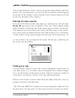
Menu off

exec

VF
Lens
Video
Install

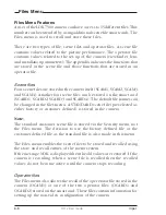
Files
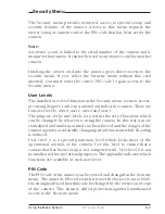
Security
Diagnostics
Service

MENU:   MAIN

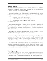
The system functions of the camera are grouped into menus and sub-
menus. The systems menu is viewed in the viewfinder and navigated
by means of  the Rotary control and the Select button which are both
located at the front of the camera.

Entering the menu system

Press the Select button after the camera is switched on, the message

Menu off

 appears in the viewfinder. Press the Select button again

while this text is showing, the Main menu appears in the viewfinder.
The Main menu screen shows five items and the name of the menu.
Four more items are hidden but become visible when you scroll down.
(Some of these items may not appear if the user level is not set to 3.)

A cursor shows your position in the menu. The Rotary control moves
the cursor up and down.

Finding your way

Use the Rotary control to move the cursor through the menu items. If
a double arrow (>>) is visible, then pressing the Select button brings
you one level lower in the menu system. Only five items are visible in
each menu. Scroll up or down to see any additional items.

When you first enter a menu (other than the Main menu) the cursor is
positioned next to the first item.

 The TOP and PREVIOUS entries are not immediately visible but are
located above the first item. Use the rotary switch to scroll up to them.

Menu System

Summary of Contents for LDK 5490

Page 1: ...User s Guide LDK 7500 LDK 5490 VIPER DIGITAL CINEMATOGRAPHIC CAMERA SYSTEM 3922 496 49801 PRINTED January 2004 ...

Page 2: ...use interference in which case the user at his own expense will be required to take whatever measures may be required to correct the interference Copyright Für diese Unterlage behalten wir uns alle Rechte vor Gemäß DIN 34 Technische Änderungen im Zuge der Weiterentwicklung vorbehalten Copying of this document and giving it to others and the use or communication of the contents thereof are forbidde...

Page 3: ...peration mode the camera operates either as a HD video camera or as a digital film camera The digital film camera mode is known as the FilmStream mode Using this manual This manual is divided into two parts Part 1 Describes how to set up and use the camera as a digital film camera in the FilmStream mode Part 2 Describes how to set up and use the camera as a HD video camera ...

Page 4: ...te optional 2 8 Shoulder Pad 2 10 Configurations 3 1 Configurations 3 2 Camera Controls 4 1 Power Supply 4 2 FilmStream Connectors 4 4 FilmStream Camera Functions 4 6 Viewfinder Indicators 4 12 System Menu Control 4 17 Auxilary Functions 4 18 Set up and operation 5 1 Setting up the camera 5 2 Operating the camera 5 4 Using the Menus 6 1 Introduction 6 2 Menu System 6 3 Menu Structure 6 6 Security ...

Page 5: ...lder Pad 2 14 Top Light option 2 15 Tripod Adapter Plate option 2 16 Configurations 3 1 Configurations 3 2 Camera Controls 4 1 Power Supply 4 2 Video Connectors 4 4 Video Functions 4 6 Viewfinder 4 12 Viewfinder Indicators 4 14 Audio 4 18 System Menu Control 4 19 Auxilary Functions 4 20 Set up and operation 5 1 Setting up the camera 5 2 Operating the camera 5 4 Shooting screens 5 10 Using the Menu...

Page 6: ...ery damp places If the environment is wet or damp a rain cover must be used to protect the unit Do not subject the unit to severe shocks or vibration Do not expose the camera to extremes of temperature Do not leave the unit in direct sunlight or close to heating appliances for extended periods Do not allow sunlight to shine into the viewfinder ...

Page 7: ...f not installed and used in accordance with the instructions may cause interference to radio communications It has been tested and found to comply with the limits for a class A digital device pursuant to part 15 of FCC rules which are designed to provide reasonable protection against such interference when oper ated in a commercial environment Operation of this equipment in a residential area is l...

Page 8: ...vi Viper ...

Page 9: ... section describes the FilmStream mode of operation and outlines the technology used in the Viper The access and security features of the camera are also explained Selecting operational mode 1 2 Streaming modes 1 3 Technology 1 4 Access and Security 1 6 Contents ...

Page 10: ...2 Go to the Install menu 3 Select Output mode item 4 Change the value to FilmStream or HDStream The camera remembers the last selected mode so it remains in the FilmStream mode even when switched off and on again Monitoring To provide a monitoring signal for viewing a separate channel is used which undergoes some video processing to make it acceptable for viewing on monitors and viewfinders Althou...

Page 11: ...d B data values using 12 bit A D converters Using logarithmic calculations this data is then converted to 10 bit values and transferred to a recorder using a dual HD SDI link Full resolution is maintained true progressive 1920 x 1080 pixels for every color No color sub sampling no color space conversions no irreversible video manipulations no further quantizations and no compression is carried out...

Page 12: ...thus providing similar motion characteristics Formats The following formats can be selected in the Install menu 1080psf at 23 98Hz 1080psf at 24Hz 1080psf at 25Hz 1080psf at 29 97Hz 1080i at 50Hz 1080i at 59 94Hz 1080i at 59 94Hz 23 720p at 23 98Hz 720p at 25Hz 720p at 29 97Hz 720p at 50Hz 720p at 59 94Hz The sensor consists of 1920 horizontal pixels and 4320 vertical sub pixels By grouping the ve...

Page 13: ...image sensor is obtained with a 16 9 aspect ratio When set to 60 frames per second slow motion effects can be achieved during post production at different playback speeds Cinemascope Aspect Ratio When three vertical sub pixels are combined 1440 vertical lines are obtained By using the middle 1080 lines a 2 37 1 aspect ratio is achieved without the need for anamorphic lenses while maintaining full ...

Page 14: ...be used as an owner s card for another camera The owner s card acts as an access control device to the security settings of the camera a storage card for four scene files and two operator files The user card stores four scene files and two operator files Operator files contain information relating to the set up of general camera preferences Scene files contain information relating to the video set...

Page 15: ...Store the owner s card in a safe place 1 1 Access control The owner s card or the PIN code is used to access special set up and security features of the camera Inserting the owner s card into the camera gives direct access to the Security menu If you select the Security menu without this card inserted you must enter the correct PIN code to gain access to this menu User levels Four user levels can ...

Page 16: ...1 8 FilmStream mode Viper ...

Page 17: ...provides information on the physical assembly of the camera and on the mounting of accessories Section 2 Assembling the Units Contents Lens 2 2 2 inch Viewfinder 2 4 Positioning the 2 inch viewfinder 2 6 Tripod Adapter Plate optional 2 8 Shoulder Pad 2 10 ...

Page 18: ...2 2 FilmStream mode Viper Lens 1 3 4 5 2 ...

Page 19: ... the lens cable into the bottom clip at the front of the camera and clip 5 located at the side Pull and twist clip 5 to open it g In the Lens menu set the Lens Type item to Std for a standard lens or to WA for a wide angle lens h Select the lens manufacturer in the Lens menu Select Ang for Angenieux Can for Canon Fuj1 or Fuj2 for Fujinon or select Other for other lens manufacturers Note Always mou...

Page 20: ...2 4 FilmStream mode Viper 2 inch Viewfinder 1 2 3 4 5 6 ...

Page 21: ...r support bracket c Tighten the locking ring 1 by turning it clockwise as seen from rear so that the viewfinder is mounted securely to the support d Connect the viewfinder cable to the viewfinder connector socket 4 at the top right of the camera e Slide the microphone holder 5 onto the viewfinder and secure with the knurled screw 6 Caution Always fit the microphone holder 5 even if you don t use a...

Page 22: ...2 6 FilmStream mode Viper Positioning the 2 inch viewfinder 1 2 3 4 5 ...

Page 23: ...king ring 1 by turning clockwise The dioptre hood and eyepiece of the viewfinder can be rotated vertically The viewfinder can be positioned backwards and forwards along the camera axis Loosen the support bracket round bar retaining lever 2 and slide the round bar 3 forwards or backwards When the desired position is reached tighten the support bracket round bar retaining lever 2 again To use the vi...

Page 24: ... mount the camera on a tripod the tripod plate LDK 5031 is available as an option must first be attached to the tripod Follow the tripod manufacturer s instructions to mount the wedge plate supplied with the tripod and the tripod adapter plate firmly onto the tripod Tripod Adapter Plate optional 1 2 3 4 5 ...

Page 25: ...E locking lever 5 to ensure that the stud 2 at the rear of the plate is locked firmly in place Caution Failure to attach the camera to the tripod adapter plate in the correct manner could result in an unsecured camera Ensure that the rear stud 2 is engaged and that the camera clicks into place To remove the camera from the tripod proceed as follows a When removing the camera first open the locking...

Page 26: ...the position of the shoulder pad press and hold lever 1 The shoulder pad can now be moved backwards and forwards along the axis of the camera Adjust the shoulder pad when all units have been mounted so that the best balanced position can be obtained 1 ...

Page 27: ...ations FilmStream mode 3 1 This section describes how the Viper can be connected to external equipment and how it can be configured with an external recorder Section 3 Configurations Contents Configurations 3 2 ...

Page 28: ...Stream RGB YUV HD SDI viewing CVBS Rec Start Tally return Cam Audio 1x Hard disks to post production SD off line recorder HD SD converter Off line tape To off line editing More audio Time code SDI Off line copy from SDI or CVBS Clear Clear A 1 Star 4P ND1 4 B 2 Star 6P ND 1 16 C 3 Soft focus ND 1 64 D 4 Break out box ...

Page 29: ... HD SDI CVBS Voodoo HD D5 HD CAM YUV HD SDI Rec Start Tally return Cam Audio 1x To post production SD off line recorder HD SD converter or Off line tape To off line editing More audio Time code On line tape SDI Clear Clear A 1 Star 4P ND1 4 B 2 Star 6P ND 1 16 C 3 Soft focus ND 1 64 D 4 ...

Page 30: ...3 4 FilmStream mode Viper ...

Page 31: ... are grouped according to their function so as to provide a quick reference guide to the operation of a particular aspect of the camera Section 4 Camera Controls Contents Power Supply 4 2 FilmStream Connectors 4 4 FilmStream Camera Functions 4 6 Viewfinder Indicators 4 12 System Menu Control 4 17 Auxilary Functions 4 18 ...

Page 32: ...ed on and off by the power at the front left of the camera The power switch has two positions On Power to camera is switched on Off Power to camera is switched off Note When you switch off the power the access rights are reset and the camera starts at the assigned user level when switched on again 1 1 4 3 5 2 6 ...

Page 33: ...r indicator lights when power is supplied to the camera and the camera power is switched on Circuit breaker button If excessive current flows the circuit breaker shuts off the power If this happens check for faults and if necessary take corrective action before pressing the circuit breaker button to reset the power Power output socket This socket provides a nominal 12 Vdc supply 20VA max for power...

Page 34: ...lmStream mode Viper DC out LCP CVBS VF Viewing channel output connector HD SDI This BNC connector supplies a serial digital video output Y Cr Cb 4 2 2 for monitoring purposes FilmStream Connectors 2 3 1 1 4 5 ...

Page 35: ...stop control signal for an external recorder is also passed via this connector FilmStream output connectors These BNC connectors together supply the dual link FilmStream output for a recording system or for a post production suite Viewfinder output connector This BNC connector supplies an analog video output signal of the viewfinder signal Markers and menus similar to those in the viewfinder can b...

Page 36: ...er 2 stops 3 ND 1 16 filter 4 stops 4 ND 1 64 filter 6 stops The inner smaller filter switch has four positions 1 Clear 2 4 point star 3 6 point star 4 Soft focus The status of the filterwheel is shown in the viewfinder for a few seconds If an ND Neutral Density filter is selected the ND RE indicator in the viewfinder lights FilmStream Camera Functions 2 3 4 5 1 1 The type of filters used in this ...

Page 37: ... shutter angle is 180 Exposure Time switch This up down momentary switch gives a choice of exposure time settings see Section 5 for more details These are Nom nominal setting CRT position for shooting sync locked monitors 1 200 for fast moving objects 1 500 for fast moving objects 50 Hz shooting with 50Hz lighting adjustable 60 Hz shooting with 60Hz lighting adjustable If an exposure time other th...

Page 38: ...and held the centre of the viewfinder picture is magnified to assist with focusing The VF Zoom Switch item in theVF menu can be used to set this button so that it operates as a latched switch Colour Temp switch White Bal This up down scroll selection switch allows a choice between four preset colour temperatures 3200K 3 2K 4700K 4 7K 5600K 5 6K 7500K 7 5K Thru for checking optical colour balancing...

Page 39: ...FilmStream mode 4 9 Gain selection switch This up down scroll selection switch gives a choice between three gain settings The indicators in the viewfinder light as follows Gain is 6dB Gain is 6dB Gain is 12dB 3 ...

Page 40: ... rear of the carrying handle When this switch is set to the ON position the front tally indicator lights when the camera is recording The front tally does not light during recording if the tally switch is set to OFF The rear tally light does not depend on the position of the tally switch if the Tally Handgrip setting in the Install menu is set to ON it lights during recording If the Tally Handgrip...

Page 41: ... be incorporated Brightness control Use this rotary control to adjust the brightness of the viewfinder display to suit your needs Contrast control Use this rotary control to adjust the contrast of the viewfinder display to suit your needs Crispening control This rotary control adjusts the sharpness of the picture displayed in the viewfinder Reduce the crispening for a better picture when the gain ...

Page 42: ... REC AW2 AW1 FL 7 5 5 6 3 2 FOC 4 7 Viewfinder Indicators Gain indicators The gain indicators along the top of the viewfinder light as follows Gain is 6dB Gain is 6dB Gain is 12dB Only applies to the monitoring signals 8 2 3 4 5 6 7 1 9 10 11 1 ...

Page 43: ... the viewfinder is switched on Flashes when viewfinder zoom is on Iris indication Indicates the value of the iris opening when enabled in the VF menu Zebra pattern This diagonal line pattern warns the operator that the area affected has risen above a predetermined level of the full scale video exposure value Level and contrast are selected in the VF menu Safe area marker The safe area marker indic...

Page 44: ...eset temperature of 5600K is selected 7 5 preset temperature of 7500K is selected FL not used in FilmStream mode AW1 not used in FilmStream mode AW2 not used in FilmStream mode Thru These indicators only show the colour temperature setting for the monitoring signal There is no white balance in the FilmStream signal ND RE BATT TAPE REC AW2 AW1 FL 7 5 5 6 3 2 FOC 4 7 8 2 3 4 5 6 7 1 9 10 11 7 ...

Page 45: ... of the VF menu Centre marker This cross marks the centre of the picture Cadre marker These dotted white lines show the limits of a 4 3 picture in the 16 9 mode Zoom indication Indicates the degree to which the lens has been zoomed in or out if this feature is supported by the lens It shows 50 if not supported 8 9 10 11 ...

Page 46: ...input for high quality condensor microphone A phantom power supply is provided for this microphone The maximum input level is 12dBu 0dBFS Only connect condenser microphones to this audio connector The sensitivity is controlled via the Install menu or LCP Audio 1 1 ...

Page 47: ... these menus gives you access to a particular group of functions More information on using the system menus is contained in Section 6 System Menu Rotary control This rotary control is used to move through the various menus of the control system It is also used to vary the value of some functions System Menu Select switch This switch when pressed selects the particular menu that is pointed out by t...

Page 48: ...iper DC out LCP CVBS VF Tally Indicators The red tally indicators light to indicate that the camera is recording LCP connector The optional Local Control Panel LCP connects to this 12 pin connector Auxilary Functions 2 1 1 2 ...

Page 49: ...de 5 1 This section contains information on the practical use of the camera It tells you how to set up and use the camera in the FilmStream mode Section 5 Set up and operation Contents Setting up the camera 5 2 Operating the camera 5 4 ...

Page 50: ...also used to display a menu style control system This menu give access to the camera functions When you first use the camera you should enter the menu system to check and if necessary select the operational mode that you wish to work in and to set up your personal preferences Refer to Section 6 Operating the Menu System which explains how to use the menu system The menu system has 3 user levels If...

Page 51: ...also set up in this menu There are also several switches and controls on the viewfinder itself for adjusting its functioning refer to Section 4 Monitoring signal To make the FilmStream signal suitable for viewing it undergoes video processing This is only for the monitoring signal the FilmStream signal is not affected Some video parameters can be changed for the monitoring signal On the camera Gai...

Page 52: ...measure stud on the lens adapter provides a reference for the optical plane To assist with optical focussing through the viewfinder use the VF Zoom button on the left front of the camera to enlarge the centre of the viewfinder image A crawler function that can be switched on or off in the VF menu adds motion in the viewfinder to objects in sharp focus Light exposure The camera has a sensitivity th...

Page 53: ...chieved by using the clean scan button Internal optical filter 23 98 24 25 29 97 50 59 94 Exposure time Nom 312 00 312 00 312 00 312 00 312 00 312 00 50Hz 172 63 172 80 180 00 215 78 180 00 215 78 60Hz 143 86 144 00 150 00 179 82 150 00 179 82 1 200 43 16 43 20 45 00 53 95 90 00 107 89 1 500 17 26 17 28 18 00 21 58 36 00 43 16 1 1000 17 26 8 64 9 00 10 79 18 00 21 58 Frames sec 23 98 24 25 29 97 5...

Page 54: ... front of the camera These filters can be used for example to control depth of field A second filter wheel in the camera contains special effect filters Start recording If your recording system supports this function you can use the Rec start button on the front or left side of the camera to start and stop the recording system The tally indicators light when recording is in progress ...

Page 55: ...menu control system It explains how to program the menu system for your personal preferences The menu structure and the methods of function selection are also explained Section 6 Using the Menus Contents Introduction 6 2 Menu System 6 3 Menu Structure 6 6 Security Menu 6 7 Files Menu 6 8 ...

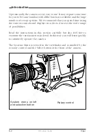
Page 56: ...e recommend that you spend time using the various controls and displays in order to discover the wide range of possibilities Read the instructions in this section carefully but also feel free to examine the various menus in detail In this way you will learn quickly to intuitively operate the camera The Systems Menu is viewed in the viewfinder and controlled by the rotorary control and the Select b...

Page 57: ... screen shows five items and the name of the menu Four more items are hidden but become visible when you scroll down Some of these items may not appear if the user level is not set to 3 A cursor shows your position in the menu The Rotary control moves the cursor up and down Finding your way Use the Rotary control to move the cursor through the menu items If a double arrow is visible then pressing ...

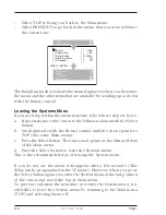
Page 58: ... a If necessary move the cursor to the leftmost column with the Select button b Scroll upwards with the Rotary control until the cursor points to TOP this is the Main menu c Press the Select button The cursor now points to the Menu off item of the Main menu d Press the Select button to leave the Systems menu This is the recommended way of leaving the System menu If you do not use the menu it disap...

Page 59: ...ailable If there are only two values associated with the function then pressing the Select button toggles between these two values If a value is displayed after the function that is part of a list then pressing the Select button places the cursor in a list menu indicating the value currently selected Use the rotary control to point to a new value Press the Select button to return the cursor to the...

Page 60: ...ffect the picture quality of the monitoring signal Install menu This menu contains functions which are used to install the camera into a particular configuration It also contains controls to customize those switches which are directly operated on the camera Files menu This menu allows function values to be stored in scene files and recalled as required Security menu The security menu is used by th...

Page 61: ...r user levels user0 user1 user2 and user3 The purpose of the user levels is to restrict the set of functions which can be changed by whoever is using the camera In this way a more centralized and uniform control can be achieved and the danger of the camera operator accidentally changing critical functions while shooting is reduced User level 0 is a special protection level which locks most of the ...

Page 62: ... and SCARD4 The default file names can be changed in the files menu A STANDARD scene file preselected as either factory or customer defined is stored in the camera Note The standard customer scene file is stored via the Security menu not the Files menu The decision to use the factory defined file or the customer defined file as the standard file is also made in this menu The Files menu enables the...

Page 63: ...ndard customer file The green button on the side of the camera recalls the standard scene file This file contains standard parameters for the picture performance A standard operator s file can be recalled via the Files menu This file contains parameters for the set up of the camera A customer standard can be defined for the standard scene file and for the standard operator s file The contents of t...

Page 64: ...6 10 FilmStream mode Viper ...

Page 65: ...s section describes the HD video mode of operation and outlines the technology used in the Viper The access and security features of the camera are also explained Selecting operational mode 1 2 HD Video mode 1 3 Technology 1 4 Access and Security 1 6 Contents ...

Page 66: ...ate the Viper as a HD video camera you have to switch modes You switch to the HD video mode by changing a menu setting for more details refer to Section 5 To change modes 1 Open the menu system 2 Go to the Install menu 3 Select Output mode item 4 Change the value to either R G B or Y Cr Cb depending on the type of output signal you require The camera remembers the last selected mode so it remains ...

Page 67: ...g tools of modern video and digital cinema cameras including adaptive knee functions matrices gammas black stretch and coarse and fine detail circuitry All other features that Viper FilmStream Cameras have to offer such as multi format capability are still available in these video modes Formats The following formats can be selected in the Install menu 1080psf at 23 98Hz 1080psf at 24Hz 1080psf at ...

Page 68: ...he sensor consists of 1920 horizontal pixels and 4320 vertical sub pixels By grouping the vertical sub pixels the vertical line count can be set Full resolution is preserved and the horizontal viewing angle stays the same 1080p When four vertical sub pixels are combined the total line count becomes 1080 lines So a 1920 x 1080 image sensor is obtained with a 16 9 aspect ratio 1080i When eight verti...

Page 69: ...mplitude 400 video RGB signals via an extended dynamic range contour circuit Colorimetry is selected by means of a variable 6 point digital matrix or via preset matrices Digital gamma circuits provide a wide range of standardised gamma curves and enable soft contrast in black scenes to be enhanced together with hard contrast and saturated colour in bright scenes The matrix and gamma sequence is so...

Page 70: ...e used as an owner s card for another camera The owner s card acts as an access control device to the security settings of the camera a storage card for four scene files and two operator files The user card stores four scene files and two operator files Operator files contain information relating to the set up of general camera preferences Scene files contain information relating to the video sett...

Page 71: ...tore the owner s card in a safe place 1 1 Access control The owner s card or the PIN code is used to access special set up and security features of the camera Inserting the owner s card into the camera gives direct access to the Security menu If you select the Security menu without this card inserted you must enter the correct PIN code to gain access to this menu User levels Four user levels can b...

Page 72: ...1 8 HD video mode Viper ...

Page 73: ...of the camera and on the mounting of accessories Section 2 Assembling the Units Contents Transport Case 2 2 Lens 2 4 2 inch Viewfinder 2 6 Positioning the 2 inch viewfinder 2 8 2 inch Viewfinder Accessories 2 10 Microphone 2 12 Shoulder Pad 2 14 Top Light option 2 15 Tripod Adapter Plate option 2 16 ...

Page 74: ...2 2 HD video mode Viper Clear Clear A 1 Star 4P ND1 4 B 2 Star 6P ND 1 16 C 3 Soft focus ND 1 64 D 4 Transport Case Top light Tripod Plate Battery Additional Supplies Packing inserts Documentation ...

Page 75: ... in the transport case as shown in the figure above This ensures that the camera is not damaged during transport Turn the 2 inch viewfinder downwards so that it does not protrude above the top of the camera Several foam packing inserts are provided to enable different configurations of the camera to be packed securely These inserts are used to support the rear of the camera Make sure you use the c...

Page 76: ...2 4 HD video mode Viper Lens 1 3 4 5 2 ...

Page 77: ...the lens cable into the bottom clip at the front of the camera and clip 5 located at the side Pull and twist clip 5 to open it g In the Lens menu set the Lens Type item to Std for a standard lens or to WA for a wide angle lens h Select the lens manufacturer in the Lens menu Select Ang for Angenieux Can for Canon Fuj1 or Fuj2 for Fujinon or select Other for other lens manufacturers Note Always moun...

Page 78: ...2 6 HD video mode Viper 2 inch Viewfinder 1 2 3 4 5 6 ...

Page 79: ... support bracket c Tighten the locking ring 1 by turning it clockwise as seen from rear so that the viewfinder is mounted securely to the support d Connect the viewfinder cable to the viewfinder connector socket 4 at the top right of the camera e Slide the microphone holder 5 onto the viewfinder and secure with the knurled screw 6 Caution Always fit the microphone holder 5 even if you don t use a ...

Page 80: ...2 8 HD video mode Viper Positioning the 2 inch viewfinder 1 2 3 4 5 ...

Page 81: ...ing ring 1 by turning clockwise The dioptre hood and eyepiece of the viewfinder can be rotated vertically The viewfinder can be positioned backwards and forwards along the camera axis Loosen the support bracket round bar retaining lever 2 and slide the round bar 3 forwards or backwards When the desired position is reached tighten the support bracket round bar retaining lever 2 again To use the vie...

Page 82: ...ptionally available wide angle eyepiece LDK 5390 00 To fit the wide angle eyepiece proceed as follows a Hold the eyepiece 1 securely b Press the button 2 below the eyepiece tube and swing it free of the button clip 3 c Press the button 4 above the eyepiece tube and remove the eyepiece d Fit the wide angle eyepiece 1 to the two clips 3 ensuring that they both click into place Wide angle eyepiece 2 ...

Page 83: ...0 to allow the viewfinder to be used with the left eye Before mounting the viewfinder onto the camera attach the left eye adapter 1 to the viewfinder and secure it using the screw 2 Do not forget to mount the microphone support bracket 3 at the end of the left eye adapter Left eye adapter 2 3 1 ...

Page 84: ...2 12 HD video mode Viper Microphone 2 3 4 5 6 7 1 ...

Page 85: ...ra and into clip 5 at the side of the camera Pull and twist clip 5 to open it Other microphones with a diameter of 21mm can also be used however ensure that the phantom power and the sensitivity of the input that match that type of microphone are correctly selected in the camera systems menu Refer to Section 6 for more information on selecting the audio inputs and controlling the audio level Note ...

Page 86: ...he position of the shoulder pad press and hold lever 1 The shoulder pad can now be moved backwards and forwards along the axis of the camera Adjust the shoulder pad when all units have been mounted so that the best balanced position can be obtained 1 ...

Page 87: ... 64 D 4 Top Light option To mount a top light 1 onto the camera proceed as follows a Screw the top light 1 into either the WW1 4 20 screw hole 2 located on the carrying handle or the screw hole on the top of the microphone holder b Power the top light according to the instructions delivered with the light 2 1 ...

Page 88: ...o mount the camera on a tripod the tripod plate LDK 5031 is available as an option must first be attached to the tripod Follow the tripod manufacturer s instructions to mount the wedge plate supplied with the tripod and the tripod adapter plate firmly onto the tripod Tripod Adapter Plate option 1 2 3 4 5 ...

Page 89: ...E locking lever 5 to ensure that the stud 2 at the rear of the plate is locked firmly in place Caution Failure to attach the camera to the tripod adapter plate in the correct manner could result in an unsecured camera Ensure that the rear stud 2 is engaged and that the camera clicks into place To remove the camera from the tripod proceed as follows a When removing the camera first open the locking...

Page 90: ...2 18 HD video mode Viper ...

Page 91: ...rations HD video mode 3 1 This section describes how the Viper can be connected to external equipment and how it can be configured with an external recorder Section 3 Configurations Contents Configurations 3 2 ...

Page 92: ...RGB YUV HD SDI viewing CVBS Rec Start Tally return Cam Audio 1x Hard disks to post production SD off line recorder HD SD converter Off line tape To off line editing More audio Time code SDI Off line copy from SDI or CVBS Clear Clear A 1 Star 4P ND1 4 B 2 Star 6P ND 1 16 C 3 Soft focus ND 1 64 D 4 Break out box ...

Page 93: ... SDI CVBS Voodoo HD D5 HD CAM YUV Video HD SDI Rec Start Tally return Cam Audio 1x To post production SD off line recorder HD SD converter or Off line tape To off line editing More audio Time code On line tape SDI Clear Clear A 1 Star 4P ND1 4 B 2 Star 6P ND 1 16 C 3 Soft focus ND 1 64 D 4 ...

Page 94: ...3 4 HD video mode Viper ...

Page 95: ...rouped according to their function so as to provide a quick reference guide to the operation of a particular aspect of the camera Section 4 Camera Controls Contents Power Supply 4 2 Video Connectors 4 4 Video Functions 4 6 Viewfinder 4 12 Viewfinder Indicators 4 14 Audio 4 18 System Menu Control 4 19 Auxilary Functions 4 20 ...

Page 96: ... power at the front left of the camera The power switch has two positions On Power to camera is switched on Off Power to camera is switched off Note When you switch off the power the access rights are reset and the camera starts at the assigned user level when switched on again 1 1 DC out LCP CVBS VF 4 3 5 2 6 ...

Page 97: ... indicator lights when power is supplied to the camera and the camera power is switched on Circuit breaker button If excessive current flows the circuit breaker shuts off the power If this happens check for faults and if necessary take corrective action before pressing the circuit breaker button to reset the power Power output socket This socket provides a nominal 12 Vdc supply 20VA max for poweri...

Page 98: ... HD video mode Viper Viewing channel output connector HD SDI This BNC connector supplies a serial digital video output Y Cr Cb 4 2 2 for monitoring purposes Video Connectors 1 DC out LCP CVBS VF 2 3 1 4 5 ...

Page 99: ...tart stop control signal for an external recorder is also passed via this connector HD Video output connectors These BNC connectors together supply the HD video output for a recording system or for a post production suite Viewfinder output connector This BNC connector supplies an analog video output signal of the viewfinder signal Markers and menus similar to those in the viewfinder can be superim...

Page 100: ...3 ND 1 16 filter 4 stops 4 ND 1 64 filter 6 stops The inner smaller filter switch has four positions 1 Clear 2 4 point star 3 6 point star 4 Soft focus The status of the filterwheel is shown in the viewfinder for a few seconds If an ND Neutral Density filter is selected the ND RE indicator in the viewfinder lights 1 1 The type of filters used in this filter wheel may vary from camera to camera ...

Page 101: ...operate in parallel with the recorder button on the lens Viewfinder Zoom button When this button is pressed and held the centre of the viewfinder picture is magnified to assist with focusing The VF Zoom Switch item in theVF menu can be used to set this button so that it operates as a latched switch Std Scene File button The standard scene file button is a momentary button which when pressed for tw...

Page 102: ...on the non standard indicator in the viewfinder lights Colour Temperature selector White Bal This up down scroll selection switch allows a choice between four preset colour temperatures 3200K 3 2K for studio lighting conditions 4700K 4 7K for studio lighting conditions 5600K 5 6K for outdoors clouded conditions 7500K 7 5K for outdoors clear blue skies three memory positions FL memory position for ...

Page 103: ... in the viewfinder lights Colour Bars switch Bars The Bars switch turns the colour bar test signal on and off The lens iris closes automatically when the colour bars are switched on Gain selection switch This up down scroll selection switch gives a choice of five master gain settings The values for these settings except 0 dB can be set in the Install menu of the camera systems menu refer to Sectio...

Page 104: ...nd so remove the noise bar When you are finished shooting the monitor press the Clean Scan button for two seconds to switch off the Clean Scan function When the Clean Scan function is on the non standard indicator in the viewfinder lights Refer to Section 5 for more information on shooting screens White Balance switch This momentary switch is used to start the automatic white balance process The c...

Page 105: ...1 500 for fast moving objects 1 1000 for fast moving objects 50 Hz shooting with 50Hz lighting adjustable 60 Hz shooting with 60Hz lighting adjustable If an exposure time other than nominal is selected the non standard indicator in the viewfinder lights Vertical Shift switch V Shift Sometimes when shooting TV screens or monitors with the same display frequency as the camera a horizontal black bar ...

Page 106: ...rear of the carrying handle When this switch is set to the ON position the front tally indicator lights when the camera is recording The front tally does not light during recording if the tally switch is set to OFF The rear tally light does not depend on the position of the tally switch if the Tally Handgrip setting in the Install menu is set to ON it lights during recording If the Tally Handgrip ...

Page 107: ...be incorporated Brightness control Use this rotary control to adjust the brightness of the viewfinder display to suit your needs Contrast control Use this rotary control to adjust the contrast of the viewfinder display to suit your needs Crispening control This rotary control adjusts the sharpness of the picture displayed in the viewfinder Reduce the crispening for a better picture when the gain i...

Page 108: ... AW2 AW1 FL 7 5 5 6 3 2 FOC 4 7 Viewfinder Indicators Gain indicators The gain indicators along the top of the viewfinder light as follows Gain is 3 or 6dB Gain is 3 6 or 9dB Gain is 6 9 or 12dB and Gain is 12 15 or 18dB 8 2 3 4 5 6 7 1 9 10 11 1 ...

Page 109: ...viewfinder is switched on Iris indication Indicates the value of the iris opening when enabled in the VF menu Zebra pattern This diagonal line pattern warns the operator that the area affected has risen above a predetermined level of the full scale video exposure value Level and contrast are selected in the VF menu Safe area marker The safe area marker indicates an area that represents 80 of the w...

Page 110: ...erature of 5600K is selected 7 5 preset temperature of 7500K is selected FL memory for fluorescent light is selected AW1 memory 1 is selected AW2 memory 2 is selected These indicators only show the colour temperature setting for the monitoring signal There is no white balance in the FilmStream signal ND RE BATT TAPE REC AW2 AW1 FL 7 5 5 6 3 2 FOC 4 7 8 2 3 4 5 6 7 1 9 10 11 7 Viewfinder Indicators...

Page 111: ...of the VF menu Centre marker This cross marks the centre of the picture Cadre marker These dotted white lines show the limits of a 4 3 picture in the 16 9 mode Zoom indication Indicates the degree to which the lens has been zoomed in or out if this feature is supported by the lens It shows 50 if not supported 8 9 10 11 ...

Page 112: ...nput for high quality condensor microphone A phantom power supply is provided for this microphone The maximum input level is 12dBu 0dBFS Only connect condenser microphones to this audio connector The sensitivity is controlled via the Install menu or LCP Audio 1 1 ...

Page 113: ...icular group of functions More information on using the system menus is contained in Section 6 System Menu Rotary control This rotary control is used to move through the various menus of the control system It is also used to vary the value of some functions System Menu Select switch This switch when pressed selects the particular menu that is pointed out by the cursor in the viefinder menu display...

Page 114: ...per Tally Indicators The red tally indicators light to indicate that the camera is recording LCP connector The optional Local Control Panel LCP connects to this 12 pin connector Auxilary Functions 1 2 DC out LCP CVBS VF 2 1 ...

Page 115: ...section contains information on the practical use of the camera It tells you how to set up and use the camera in the HD video mode Section 5 Set up and operation Contents Setting up the camera 5 2 Operating the camera 5 4 Shooting screens 5 10 ...

Page 116: ...so used to display a menu style control system This menu give access to the camera functions When you first use the camera you should enter the menu system to check and if necessary select the operational mode that you wish to work in and to set up your personal preferences Refer to Section 6 Operating the Menu System which explains how to use the menu system The menu system has 3 user levels If t...

Page 117: ...nu The zebra overexposure indicators and the focus assist function are also set up in this menu There are also several switches and controls on the viewfinder itself for adjusting its functioning refer to Section 4 Video preferences The camera is now ready for use however the ambient conditions must now be taken into account and the appropriate adjustments made on the camera a Recall the standards...

Page 118: ...tandard values only take effect when the camera is not recording Note The standard file can be selected as either a factory or a customer standard file Changing the standard file can only be done in the System security menu if the owner card or the PIN code is used Colour Bar The left side panel also contains a button for switching on the colour bar test signal The colour bar is a standard test si...

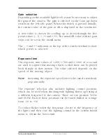
Page 119: ...ed Exposure time The exposure time values of 1 200 1 500 and 1 1000 of a second are used to capture fast moving objects so that these can be played back sharply in slow motion The value selected depends on the speed of the moving object Note Increasing the exposure speed lowers the camera sensitivity proportionally The exposure selection also includes lighting control positions which can be used w...

Page 120: ... ambient lighting conditions must be compensated for by selecting a value for the colour temperature The standard file setting is 3200K normally used for tungsten light Two other reference colour temperatures are available 5600K for outdoors clouded conditions and 7500K for outdoors clear blue skies Three similar memory positions FL AW1 and AW2 are available to store the results of the auto white ...

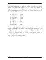
Page 121: ... balance 4700K White balance 5600K White balance 7500K White balance FL White balance AW1 White balance AW2 White balance AWC The viewfinder displays the selected value and the actual measured colour temperature The range of the auto white balance is from 2 5K to 20K In the auto white positions an electronic colour filter can be adjusted in the system Video menu This varies the colour balance to o...

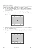
Page 122: ...b Press once on the white balance switch at the front of the camera to start the automatic white balance procedure The following appears in the viewfinder c Point the camera so that the reference white surface is between the two small white boxes d Press the white balance button again to start the measurement procedure A message indicating that the process is runnning appears ND RE BATT TAPE REC A...

Page 123: ...ady for use Start recording If your recording system supports this function you can use the Rec start button on the front left of the camera to start and stop the recording system The tally indicators light when recording is in progress Focussing To assist with optical focussing through the viewfinder use the VF Zoom button on the left front of the camera to enlarge the centre of the viewfinder im...

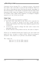
Page 124: ...Carry out the Clean Scan function as follows a press the Clean Scan button at the front of the camcorder for about two seconds to directly access the variable exposure clean scan function The Clean Scan submenu appears in the viewfinder b Use the rotary control to change the value and so remove the horizontal black bar c Set the Unit item to the prefered read out Hz mSec or degrees When you are fi...

Page 125: ...der This function is only active when the camera is not genlocked and when it is not on air If the frame frequencies of camera and monitor are different use the clean scan function CRT Exposure A third possibility can arise when shooting a monitor whose synchronization is locked to the camera s Stripes might be visible in the picture of the monitor This is more usual with 16 9 cameras To remove th...

Page 126: ...5 12 HD video mode Viper ...

Page 127: ...ol system It explains how to program the menu system for your personal preferences The menu structure and the methods of function selection are also explained Section 6 Using the Menus Contents Introduction 6 2 Menu System 6 3 Menu Structure 6 6 Security Menu 6 7 Files Menu 6 8 Install Menu 6 10 ...

Page 128: ...er to discover the wide range of possibilities Read the instructions in this section carefully but also feel free to examine the various menus in detail In this way you will learn quickly to intuitively operate the camera The Systems Menu is viewed in the viewfinder and controlled by the rotorary control and the Select button at the front of the camera Clear Clear A 1 Star 4P ND1 4 B 2 Star 6P ND ...

Page 129: ...reen shows five items and the name of the menu Four more items are hidden but become visible when you scroll down Some of these items may not appear if the user level is not set to 3 A cursor shows your position in the menu The Rotary control moves the cursor up and down Finding your way Use the Rotary control to move the cursor through the menu items If a double arrow is visible then pressing the...

Page 130: ...a If necessary move the cursor to the leftmost column with the Select button b Scroll upwards with the Rotary control until the cursor points to TOP this is the Main menu c Press the Select button The cursor now points to the Menu off item of the Main menu d Press the Select button to leave the Systems menu This is the recommended way of leaving the System menu If you do not use the menu it disapp...

Page 131: ...ilable If there are only two values associated with the function then pressing the Select button toggles between these two values If a value is displayed after the function that is part of a list then pressing the Select button places the cursor in a list menu indicating the value currently selected Use the rotary control to point to a new value Press the Select button to return the cursor to the ...

Page 132: ...fect the picture quality of the output signal Install menu This menu contains functions which are used to install the camera into a particular configuration It also contains controls to customize those switches which are directly operated on the camera Files menu This menu allows function values to be stored in scene files and recalled as required Security menu The security menu is used by the cam...

Page 133: ... user levels user0 user1 user2 and user3 The purpose of the user levels is to restrict the set of functions which can be changed by whoever is using the camera In this way a more centralized and uniform control can be achieved and the danger of the camera operator accidentally changing critical functions while shooting is reduced User level 0 is a special protection level which locks most of the o...

Page 134: ...and SCARD4 The default file names can be changed in the files menu A STANDARD scene file preselected as either factory or customer defined is stored in the camera Note The standard customer scene file is stored via the Security menu not the Files menu The decision to use the factory defined file or the customer defined file as the standard file is also made in this menu The Files menu enables the ...

Page 135: ...dard customer file The green button on the side of the camera recalls the standard scene file This file contains standard parameters for the picture performance A standard operator s file can be recalled via the Files menu This file contains parameters for the set up of the camera A customer standard can be defined for the standard scene file and for the standard operator s file The contents of th...

Page 136: ... these symbols This is done in the Install menu Disable camera The disable camera function is a protection function which prevents unathorised interference with the camera and provides an additional level of security Setting disable camera to ON is similar to using User level 0 to protect the settings of the camera Install Menu ...

Reviews: