background image

Instructions and Parts

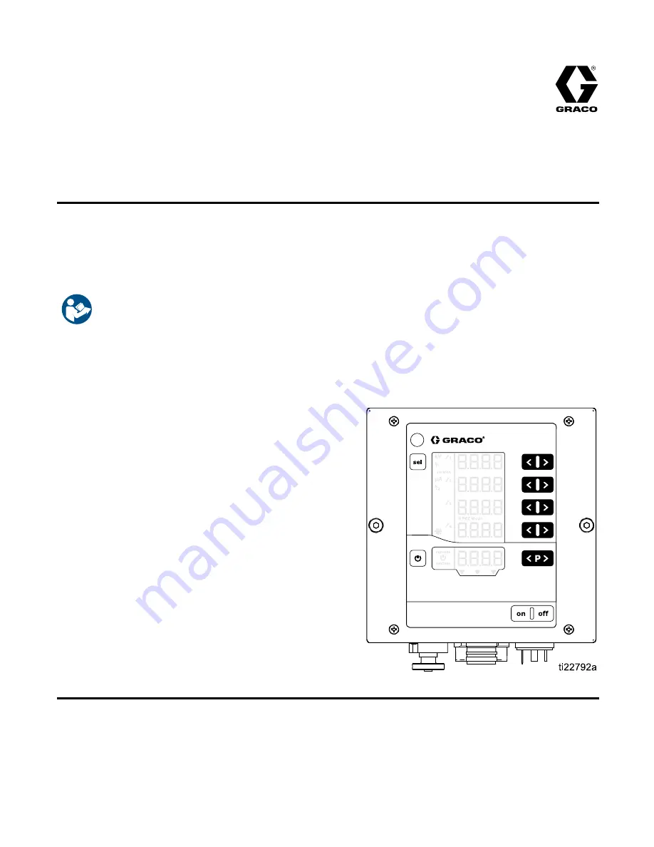
ProBell® Electrostatic Controller

3A3657C

EN

For controlling a ProBell rotary applicator as part of a paint coating system. For professional use only.

Not approved for use in explosive atmospheres or hazardous locations.

Important Safety Instructions

Read all warnings and instructions in this manual and in your

ProBell® Rotary Applicator manual. Save these instructions.

PROVEN QUALITY. LEADING TECHNOLOGY.

Summary of Contents for ProBell Electrostatic Controller

Page 1: ...as part of a paint coating system For professional use only Not approved for use in explosive atmospheres or hazardous locations Important Safety Instructions Read all warnings and instructions in thi...

Page 2: ...and Features 38 Screen Areas 38 Icons 38 Input Keys and Switches 39 Additional Features 39 Setup 41 Setup Screen 0 System Type 43 Setup Screen 1 Electrostatics Control Mode 43 Setup Screen 2 Remote In...

Page 3: ...Power Supply Cables Product Type System Approvals 17J586 17J588 RxAxx0 24Z098 17J589 Solventborne 17J586 17J588 RxAxx8 24Z099 17J589 Waterborne Related Manuals Manual No Description 334452 ProBell Rot...

Page 4: ...ll discharge the system voltage when not in use All components of the voltage isolation system that are charged to high voltage must be contained within an isolation enclosure that prevents personnel...

Page 5: ...rces such as pilot lights cigarettes portable electric lamps and plastic drop cloths potential static arc Do not plug or unplug power cords or turn lights on or off when ammable fumes are present Keep...

Page 6: ...n or damaged parts immediately with genuine manufacturer s replacement parts only Do not alter or modify equipment Alterations or modi cations may void agency approvals and create safety hazards Make...

Page 7: ...that is safe for the system to operate Electrostatic controller and solvent trigger Interlock so that solvent will not ow when the electrostatics are on Electrostatic controller and all doors or openi...

Page 8: ...ot satis ed electrostatics disabled 1 24 VDC interlock satis ed electrostatics activation is not locked by this input If not required apply a constant 24 VDC to Pin 19 or see Disable Controller Interl...

Page 9: ...nterlock Pin 18 on the Discrete I O cable Symbols in A9 and A10 see Screen Areas page 38 on the display screen will show that these signals are satis ed ON GOHO2 Interlock switches are shown in the OF...

Page 10: ...e Electrostatic Controller Local operation using the Electrostatic Controller interface Interlocks managed independently of the applicator installation Non Hazardous Location Hazardous Location KEY A...

Page 11: ...P002 by applying 24V to Pin 2 and Ground or no connection to Pin 1 Remote Enable Disable Pin 4 Enable remote control through the Discrete I O interface by applying 24V to Pin 4 Electrostatic Enable Pi...

Page 12: ...ion of the signals KEY A Electrostatic Controller B Electrostatic Controller Ground Wire C Electrostatic Controller Power Cord D CAN Cable E Power Supply Cable F Rotary Applicator G PLC Communication...

Page 13: ...Installation Non Hazardous Location Hazardous Location Typical Installation With PLC Integration 3A3657C 13...

Page 14: ...ventilator interlock Check and follow all National State and Local codes regarding air exhaust velocity requirements NOTE High velocity air exhaust will decrease the operating ef ciency of the electr...

Page 15: ...o be used to attach the controller to the panel the panel holes will require tapping threads or providing some other sort of threaded fastener such as PEM nuts on the panel b If an alternative fastene...

Page 16: ...y connecting a ground wire and clamp as described in your separate pump instruction manual Voltage Isolation System for waterborne systems Follow the grounding procedure in the manufacturer s instruct...

Page 17: ...E Discrete I O Cable Connection use in a system that requires integration BB Enclosure FF Applicator Power Cable Connection CC Front Plate with control and display elements GG Ground Connection DD Inp...

Page 18: ...fy the system interlock When the system interlock pin is connected to line voltage the icon will appear on the controller See Screen Areas page 38 3 Connect the 7 pin end of the power cable to the app...

Page 19: ...nication is used connect supplied ferrites to CAN cables near the electrostatic controller see below Discrete I O cable Connection Pin No Function Wire Color 1 Preset Select 1 Input White 2 Preset Sel...

Page 20: ...ust be selected by setting Parameter P02 1 See Setup Screen 2 Remote Interface page 44 The REMOTE Enable input on the Discrete I O cable pin 4 must have 24 VDC logical 1 applied to it to select REMOTE...

Page 21: ...possible to change the values of these Presets remotely Presets P004 P250 are not accessible in REMOTE mode 3 Digital Input Error Reset Input Use to allow error codes to be acknowledged remotely Ackno...

Page 22: ...up Screen 5 Digital Output Type Select page 46 8 Ground I O Ground Reference potential for I O interface signals 9 Analog Input Current Setpoint Input Use to set the current setpoint A nominal value T...

Page 23: ...pin the greater the output voltage at the applicator 0 max kV applicator output 0 10V or 4 20 mA pin output The type of output is selected on Setup Screen 4 Analog Output Type Select page 45 max kV 10...

Page 24: ...tatics disabled If electrostatics are on no change to electrostatics 1 Interlock satis ed electrostatics activation is not locked by this input NOTE Switching from 1 to 0 does not deactivate electrost...

Page 25: ...s Input current limit Yes 25 mA Accuracy 1 typical Analog Outputs The analog outputs are used to communicate actual values to other devices such as a PLC The outputs can be con gured to be either volt...

Page 26: ...VDC voltage to be connected to Output External Power discrete I O interface pin 16 Electrical Speci cation Use Parameter P05 see Setup Screen 5 Digital Output Type Select page 46 to select the output...

Page 27: ...are shown here 1 2 3 4 5 11 18 19 8 12 17 24VDC GND Figure 1 Digital Inputs 9 10 0 10V OR 4 20mA Figure 2 Analog Inputs 6 7 15 8 12 17 24VDC GND Figure 3 Digital Outputs Sinking Mode 6 7 15 8 12 17 24...

Page 28: ...ams use 0 to indicate a signal or function is off or inactive and 1 to indicate a signal or function is on or active A spray system has several modes of operation These modes describe the system state...

Page 29: ...ed when any or a combination of the following signals are inactive System interlock power connector 24 VDC Interlock Electrostatic Enable NOTE The SAFE POSITION input does not deactivate electrostatic...

Page 30: ...TION and that the electrostatics can be activated 4 Set the Electrostatic Enable input high or activate the electrostatics 5 The Electrostatic Controller activates the electrostatics at the applicator...

Page 31: ...Timing Diagram System Interlock Input 24 VDC Interlock Input REMOTE Enable Disable SAFE POSITION Interlock Input Electrostatics Enable Electrostatics Safe to Move Output Active Inactive Input Output t...

Page 32: ...page 48 6 Change the desired electrostatic output a If spraying in local mode using the Electrostatic Controller interface change the active Preset P000 P003 using the keys Set the voltage and current...

Page 33: ...etpoints Electrostatic Enable Electrostatics Safe To Move Output Electrostatics Discharged Output Active Inactive Input Output L Any method used to disable electrostatics M Setting Change tC1 Blanking...

Page 34: ...dure 1 Fix the condition that caused the error code see Troubleshooting page 61 2 Acknowledge the error code a If using the discrete I O interface acknowledge the error code using Discrete I O Error R...

Page 35: ...s Safe to Move Output Active Inactive Electrostatics Discharged Output Active Inactive Fluid Supply Part Conveyor Applicator Movement Input Output A Hold high until error output is low B Fix error con...

Page 36: ...ble pin This can also be accomplished by powering down the controller Disable the electrostatics any time the solvent supply is activated Before enabling electrostatics again ensure that the paint and...

Page 37: ...nput SAFE POSITION Interlock Input Electrostatic Enable Input Solvent Supply Paint Supply Electrostatics Enabled Disabled Electrostatics Discharged Output Active Inactive Input Output Not controlled b...

Page 38: ...mation A6 REMOTE operation enabled A7 Electrostatics active triggered A8 System interlock connection satis ed A9 SAFE POSITION Interlock satis ed A10 24 VDC Interlock satis ed A11 Electrostatic Enable...

Page 39: ...continues to allow Preset selection Display of preset values of the current Preset Display of the actual values Error acknowledgement Activate deactivate the keyboard lock 1 Press the key and the T8 k...

Page 40: ...Maintenance counts state active non active and setpoints are NOT reset NOTE By restoring factory defaults except for display backlight setting all user made settings will be set to factory default 1 P...

Page 41: ...Setup Screen Display A1 Value Description Display A3 Values Display A4 Value 0 P00 Applicator Type Display A2 APP Use to de ne applicator type and features This selection is set in the factory and ca...

Page 42: ...l that the controller will use to calculate the dynamic arc 0 01 1 00 by 0 01 0 10 default 9 C1 Arc detection blanking time setpoint sec Use to set the amount of time after turning on the high voltage...

Page 43: ...ot be changed NOTE This parameter is not overwritten if a Factory Default Reset is performed Std Solventborne product 100 kV maximum UUb Waterborne product 60 kV maximum Setup Screen 1 Electrostatics...

Page 44: ...ed local operation 1 dio Discrete I O interface is enabled This selection is the default See Discrete I O page 20 for more information 2 CAn CAN interface is enabled The CAN interface is used to commu...

Page 45: ...point analog inputs for the Discrete I O interface See Discrete I O page 20 for more information Setup Screen 4 Analog Output Type Select Use Setup Screen 4 Parameter P04 to select the output signal t...

Page 46: ...r Output and the Electrostatic Discharge Output pins on the Discrete I O Interface See Discrete I O page 20 for more information NOTE The controller must be restarted for a change to this parameter to...

Page 47: ...Update page 68 The controller can export log reports of controller activity to an installed micro SD card for test purposes and for nding defects NOTE If a micro SD card is present when the controlle...

Page 48: ...aterborne Default is 10 0 not shown Setup Screen 10 Discharge Timer Use Setup Screen 10 Con guration C2 to select the time in seconds from when the electrostatics are disabled until the electrostatics...

Page 49: ...nged If arc detection errors occur when the voltage or current setpoint is changed increase the transition time or adjust the Arc Detection parameters to be less sensitive see Arc Detection page 54 Us...

Page 50: ...Run Screens after 5 seconds have elapsed since the last keystroke the display will revert to Run Screen 1 Presets The Electrostatic Controller has 251 P000 P250 user de ned Presets There are four val...

Page 51: ...en the electrostatics are active triggered Actual values are displayed in green Use this screen to set the voltage A1 and current A2 set points for each Preset The set point is displayed in black Set...

Page 52: ...ded object that is stationary or slow moving The dynamic arc limit is used to detect grounded object that is fast moving For both static and dynamic arc limits lower values are more sensitive than hig...

Page 53: ...itoring press the corresponding and simultaneously for a deactivated counter During the rst activation a value of 1 is shown as the start value If monitoring has already been activated at some earlier...

Page 54: ...r stationary reciprocator systems and then for robot mounted systems For Stationary Systems and Reciprocators Follow the general procedure for robot mounted systems next section but manually approach...

Page 55: ...his setting adds to the sensitivity achieved by setting the Dynamic Arc Limit itself The default averaging threshold is adequate for most applications If nuisance errors are seen when triggering or de...

Page 56: ...xceeds arc detection limit setpoint When an arc detection error occurs the live arc detection values freeze on the screen This will tell you what the maximum arc detection values were when the error o...

Page 57: ...d for 5 seconds from any SETUP screen Also shown on power up Press and hold for 5 seconds from any RUN screen Or press from SETUP SCREENS 8 11 Screens that are not implemented for the Electrostatic Co...

Page 58: ...Screen Map RUN SETUP SCREENS 0 7 Parameters SETUP SCREENS 8 11 Con gurations T1 T2 T1 T2 T1 T2 T1 T2 T1 T2 T1 T2 58 3A3657C...

Page 59: ...Screen Map RUN SETUP SCREENS 0 7 Parameters SETUP SCREENS 8 11 Con gurations T1 T2 T1 T2 T1 T2 3A3657C 59...

Page 60: ...Screen Map RUN SETUP SCREENS 0 7 Parameters SETUP SCREENS 8 11 Con gurations T1 T2 60 3A3657C...

Page 61: ...rvoltage Measured voltage output is greater than 105 kV Stop Verify system grounding Verify applicator power cable connection and perform Power Cable Continuity page 64 Replace applicator power cable...

Page 62: ...lue Initialize defaults H25 Memory write timeout Writing to EEPROM takes longer than 10ms None Verify all connections inside of controller are properly made Replace main board if necessary H26 Memory...

Page 63: ...tion error No response timeout to a request Error report on command execution Response data mismatch None H92 Bell controller not alive Heartbeat message timeout Stop Verify all connections inside of...

Page 64: ...error Unspeci ed fatal error Restart Verify that all connections inside of the controller are properly made Restart controller Verify software version and upgrade if needed Replace main board if nece...

Page 65: ...he circuit boards when servicing the control box wear Part No 112190 grounding strap on your wrist and ground appropriately each time Main Circuit Board Power Board LED Panel or Keypad Membrane Remova...

Page 66: ...isconnect the three remaining cables 5 Lift the main board carefully out of the module 6 Remove four nuts and washers Lift the power board carefully out of the module 7 Remove 4 spacers then remove th...

Page 67: ...4 Gently pry the power board from the four retaining clips and remove the board as shown CAN Board Removal 1 Remove power from the system 2 Remove four screws then remove the controller access cover...

Page 68: ...remove power from the system 3 Remove four screws then remove the controller access cover 4 Find the micro SD card slot on the top of the main board and insert the microSD card with the software upda...

Page 69: ...e system only 17H286 Power Board 17H285 Power Supply Board 17H283 Button Panel 17H282 LCD Panel 25C427 CAN Board Accessories Power Cables Part No Description 17J586 Power Cable 36 ft 11 m 17J588 Power...

Page 70: ...Dimensions Dimensions Controller 70 3A3657C...

Page 71: ...Dimensions Flush Mount 6 26 in 15 9 cm 5 71 in 15 0 cm 7 65 in 19 4 cm 3 30 in 8 4 cm M6 X 1 mm Wall Mount Bracket 17H288 3A3657C 71...

Page 72: ...Notes Notes 72 3A3657C...

Page 73: ...oltage to the applicator eff 10V Nominal Output Current to the applicator max 1 2 A External Power Requirements 100 240 VAC 50 60 Hz 1 amp maximum draw 15 amp maximum circuit breaker recommended Prote...

Page 74: ...ges for lost pro ts lost sales injury to person or property or any other incidental or consequential loss shall be available Any action for breach of warranty must be brought within two 2 years of the...

Reviews: