background image

3A7526B

EN

Setup - Operation - Repair

PR-X

Fixed Ratio System

For accurate metering, mixing, and dispensing of two-component materials. For 
professional use only.

Not approved for use in explosive atmospheres or hazardous (classified) locations. 

1200 psi (8.3 MPa, 83 bar) Maximum Working Pressure
100 psi (0.7 MPa, 7 bar) Maximum Air Inlet Pressure

Important Safety Instructions

Read all warnings and instructions in this 
manual before using the equipment. 
Save these instructions. 

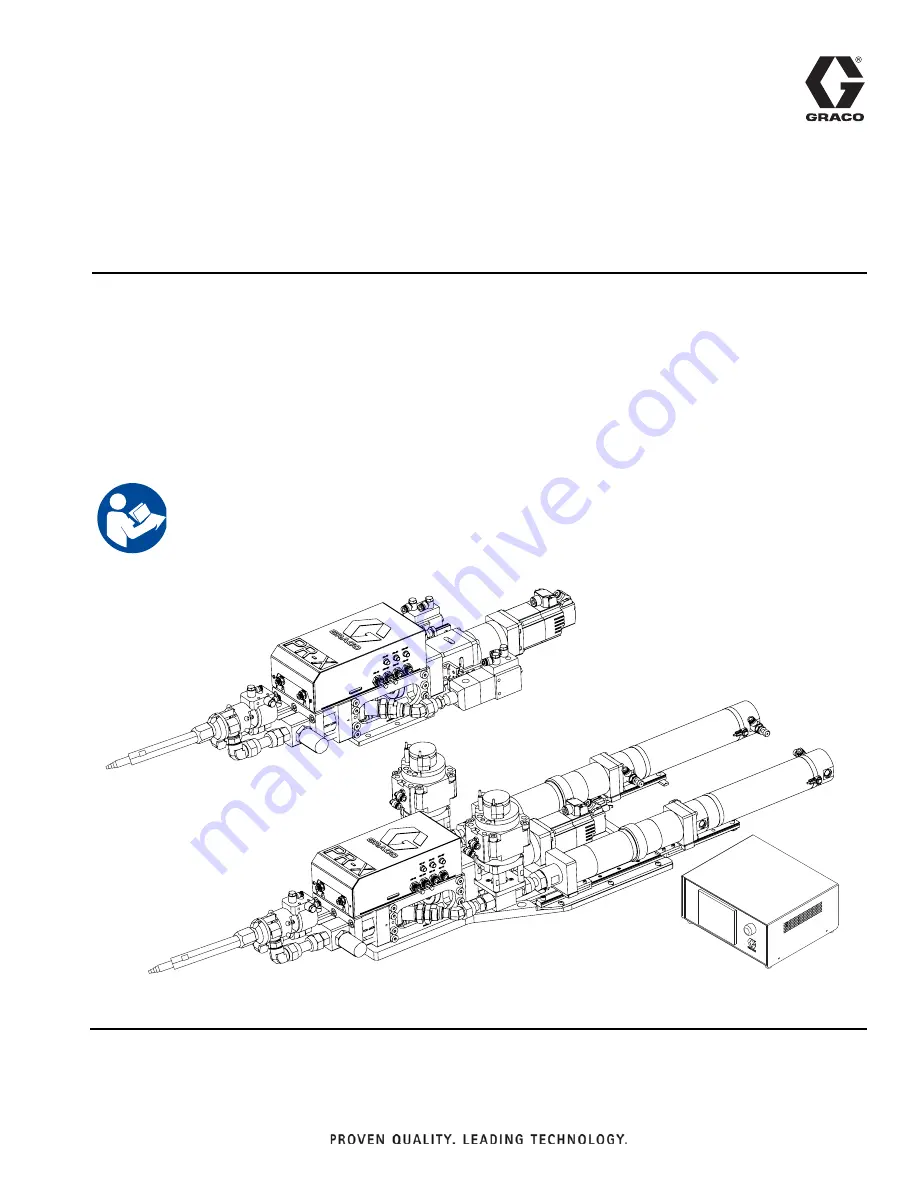
PR-X Machine, Supply 
Pump Feed, MD2 Dispense 
Valve Direct Shown

PR-X Machine, Cartridge 
Feed, MD2 Dispense 
Valve Direct Shown

PR-X Control Box

Summary of Contents for 25R128

Page 1: ...or hazardous classified locations 1200 psi 8 3 MPa 83 bar Maximum Working Pressure 100 psi 0 7 MPa 7 bar Maximum Air Inlet Pressure Important Safety Instructions Read all warnings and instructions in...

Page 2: ...lush the Equipment 46 Software Setup For Profinet Communication Mode Only 47 Maintenance 51 Preventive Maintenance 51 Recycling and Disposal 52 End of Product Life 52 Troubleshooting 53 Repair 56 Prep...

Page 3: ...stems If you want to order other ratio systems 1 1 2 4 1 please contact Graco sales representative for a custom solution Part Description Includes PR X Machine PR X Control Box 4 MD2 Dispense Valve St...

Page 4: ...ian and comply with all local codes and regulations SKIN INJECTION HAZARD High pressure fluid from dispensing device hose leaks or ruptured components will pierce skin This may look like just a cut bu...

Page 5: ...Use equipment only in well ventilated area Eliminate all ignition sources such as pilot lights cigarettes portable electric lamps and plastic drop cloths potential static sparking Ground all equipment...

Page 6: ...om traffic areas sharp edges moving parts and hot surfaces Do not kink or over bend hoses or use hoses to pull equipment Keep children and animals away from work area Comply with all applicable safety...

Page 7: ...Control Box K Supply Pump System A L Supply Pump System B M Customer Robot N Customer Control Box P I O Communication Cable R Profinet Communication Cable S Junction Box cable T Pressure Sensor A Cab...

Page 8: ...E MD2 Dispense Valve AF Direct Connection 1 AG Remote Hose Connection 2 AH Static Mixer Package AJ Nose Piece AK PR X Bottom Plate AL Inlet Valve 1K Ultra Lite Valve 3 AS Leaking Hole 1 For direct ver...

Page 9: ...Remote Hose Connection 2 AH Static Mixer Package AJ Nose Piece AK PR X Bottom Plate AM Inlet Valve 3 AN Cylinder Assembly 3 AP Cartridge Sleeve Nut 3 AR Cartridge Sleeve Assembly 3 AS Leaking Hole 1...

Page 10: ...tion BD Junction Box Connection BE Pressure Sensor A Connection BF Pressure Sensor B Connection BG Remote Ethernet Connection BH Servo Encoder Connection BJ Start Signal Connection BK Servo Motor Conn...

Page 11: ...t your Graco distributor or Graco China Customer Service for assistance in designing a system to suit your specific needs Installation Unpacking 1 Inspect the shipping container carefully for damage C...

Page 12: ...onto the designated location 3 Attach the PR X Bottom Plate AK to the selected location by installing fasteners not provided with the PR X machine through the four mounting holes There are also two p...

Page 13: ...le Dimensions for Installing the PR X Machine Cartridge Feed 6 x 0 4 in 9 mm Through 0 6 in 15 5 mm 0 4 in 9 mm 5 1 in 130 mm 3 2 in 80 mm 2 x 0 3 in 8 mm 0 3 in 8 mm 1 6 in 40 mm 6 3 in 159 mm 7 9 in...

Page 14: ...ace hose immediately Air compressor follow manufacturer s recommendations MD2 Dispense Valve AE ground through connection to a properly grounded fluid hose and pump Fluid supply container follow local...

Page 15: ...single phase to the Power Connection BN on the back of PR X Control Box J 4 Use cables to connect junction box pressure sensor A and B servo motor power and servo motor encoder from the PR X Machine H...

Page 16: ...the start screen after Start is selected in the Start Center screen Automatic Screen 1 see page 19 Automatic Screen 2 see page 22 Automatic Screen 3 see page 23 Automatic Screen 5 see page 26 Automat...

Page 17: ...ued Advanced Screen 1 see page 41 Advanced Screen 2 see page 42 System Main Screen see page 28 Manual Screen 1 see page 29 Manual Screen 2 see page 30 Manual Screen 3 For Cartridge Version Only see pa...

Page 18: ...Bead see page 33 Setup Screen 6 Pre charge see page 35 Setup Screen 5 Purge see page 34 Setup Screen 4 Sequence see page 33 Setup Screen 7 De pressurization see page 36 Advanced Setup Screen 1 see pag...

Page 19: ...ob start signal must be 1 during one job In sequence mode step 0 to step 15 will be considered one job Ready Pre charge has been completed and the system is ready to dispense material Dispensing The s...

Page 20: ...d before dispense starts The sequence includes 16 steps maximum and the operator can edit step 1 to 14 as step 0 and 15 are reserved respectively for pre charge and depressurization When Enable Sequen...

Page 21: ...based on rate command Sequence mode In Sequence mode the step number remaining repeat times target flow rate and volume will be shown in different screens based on different step types The operator ca...

Page 22: ...ignals Servo ON This signal will be shown as green after system start Servo ready Motor can be used or is working without problem Servo alarm Something is wrong with the motor Operator should push the...

Page 23: ...o reduction time will be shown in box If the timer times out the system will automatically reduce the pressure and end the current job HOME button This is the return to the Home point command When the...

Page 24: ...4 00100 Error Pre charge time out 5 00101 Error Pressure relief time out 6 00110 Error Reload time out 7 00111 Error Servo fault 8 01000 Error Part A Supplier is in low level 9 01001 Error Part B Sup...

Page 25: ...integer and the unit is psi Disp press B Current working pressure value of part B The value from the PR X control box is an integer and the unit is psi MTR torque Current driver motor working torque T...

Page 26: ...d version press F4 or select the button to return to the Automatic Screen 1 The content and functions of this screen are as follows Select box After one or several selection boxes are selected the Res...

Page 27: ...vice A or B regardless of supply type supply pump feed or cartridge feed Part A or B smart feed Only activate to drive supply device in reloading For supply pump feed the system will start the pump on...

Page 28: ...e entered to visit the Setup Screens To open the Advanced mode the operator must enter the password 1492 The Advanced option won t show until the password has been entered Select System Relief button...

Page 29: ...and Purge Flowrate and target volume Parameter setting of flow rate and target volume Progress bar and actual dispense volume Shot mode Displays the progress bar showing the completion of the current...

Page 30: ...to check the signal exchange only Manual Screen 3 For Cartridge Version Only On the Manual Screen 3 press F1 or select the button to display the Manual Screen 2 Press F4 or select the button to retur...

Page 31: ...activate to change cartridge after the job is finished Select Cart Change to move back the cartridge cylinder rod Press F3 to move forward the cartridge cylinder rod Setup Screen Setup Screen 1 Reloa...

Page 32: ...reload automatically The system will reload only when prompted by external signal Reload request position When the material in the supply pump system or supply cartridge is less than the percentage s...

Page 33: ...or should set Max Rate first The Operator can use 0 10 V signal to control flow rate Setup Screen 4 Sequence On the Sequence Setup Screen press F1 or select the button to display the System Main Scree...

Page 34: ...rge volume Set the target purge volume Purge rate Set the purge flowrate Purge alarm time Set the purge request timer When the equipment doesn t dispense the PR X control box will start the countdown...

Page 35: ...the set time the system will activate the alarm to alert the operator the limit has been reached Pre charge speed The operator may set two separate pre charge rates The system will pre charge at the...

Page 36: ...ed NOTE Set different depressurization targets according to different materials For detailed information please contact your Graco distributor Max depressurization time The operator may set a maximum...

Page 37: ...c minute or cc second from the dropdown list to customize the units used for flowrate setup Pressure unit The operator may select psi bar or MPa from the dropdown list to customize the units used for...

Page 38: ...be able to change working mode using the touch screen Style No selected by The operator may choose whether the style number may be changed by Display Distributed IO or Gateway Dispense CMD resource Th...

Page 39: ...trol box Enable sequence mode If this function is selected the PR X system will run in sequence mode In this mode the operator can edit the working sequence The sequence includes 16 steps maximum The...

Page 40: ...tions of this screen are as follows Pressure sensor offset The operator may input values to adjust the pressure offset on the sensors Pressure limit If the Part A or B pressure is higher than the pres...

Page 41: ...t individually For this reason only qualified personnel who have received equipment maintenance training should be authorized to navigate to this screen and perform system check The content and functi...

Page 42: ...ense Valve AE is open the button will be green when the MD2 Dispense Valve AE is closed the button will be gray Inlet valve A and inlet valve B Selecting each of these buttons enables testing of inlet...

Page 43: ...E If needed add the pressure relief valve to reduce pressure to 100 psi 0 7 MPa 7 bar 4 Perform Prime the System on page 44 5 Perform the Ratio Check Procedure on page 45 6 Install Static Mixer Packag...

Page 44: ...the sensor sends out the stop signal then set the move speed to 0 2 cc s 4 Select Dispense valve Inlet valve A and Inlet valve B to turn on MD2 Dispense Valve AE and Inlet Valve A and B AL or AM 5 Wh...

Page 45: ...ed when the density or specific gravity of both the A and B components are known and only one of the ratios Example A material has a weight ratio of 10 1 the A material has a specific gravity of 1 20...

Page 46: ...d with compatible solvent before introducing a new fluid Use the lowest possible pressure when flushing All fluid components are compatible with common solvents To flush the entire system circulate th...

Page 47: ...P address Insert the SD card 1 Turn off the control box power 2 Remove the control box cover 3 Insert the SD card PLC IP Address Setup 1 Start PR X control box and push Settings button on the Start Ce...

Page 48: ...een HMI will then find PLC in the Net Select the device with the IP address you want to change Then select to proceed the next screen 6 Edit IP address directly on the Step 3 4 screen Then select to p...

Page 49: ...ide item on the Step 2 3 screen Then select to proceed to the next screen 11 Select Accept on the Step 3 3 screen 12 Return to the Start Center screen and restart HMI before HMI IP address setup HMI I...

Page 50: ...Operation 50 3A7526B 3 Edit IP address directly from the Network Interface screen 4 Return to the Start Center main screen and restart HMI...

Page 51: ...upply pump or cartridge 3 Clean dust and foreign matter from the PR X machine and the PR X control box 4 Inspect fluid lines and adapters for leaks 5 Inspect inlet air filter equipment expel water and...

Page 52: ...rocedure on page 46 Drain and dispose of fluids according to applicable regulations Refer to the material manufacturer s Safety Data Sheet Remove motors circuit boards LCDs liquid crystal displays and...

Page 53: ...stem Significant material leaking from pump seal Pump shaft and or shaft seal worn Remove pump shaft assembly and reinstall pump rebuild kit Material weight incorrectly dispensed Needle or Static Mixe...

Page 54: ...Mixer Package AH and or needle with a bigger gauge 2 Slow down dispensing speed to decrease working pressure continuous and stable dispensing pressure should be within a range of 150 400 psi Pressure...

Page 55: ...Wrong Dispense mode Choose correct mode Wrong Dispense type Choose correct type Wrong mode and or type trigger method Choose correct trigger method in Setup menu job can be trigged by outside signal...

Page 56: ...essure drops to ZERO 3 Go to the Advanced Screen of the PR X control box J Set the move speed at about 0 2 cc s then jog select Piston move down until the lower switch light is activated NOTE To open...

Page 57: ...er end caps 106 6 Carefully slide the end of the cylinder into the cylinder housing 10202a in the correct direction Ensure the cylinder doesn t damage the sides of the piston as the cylinder is insert...

Page 58: ...ly Pump Feed 63 6 PR X Base Assembly Supply Cartridge Feed 64 6 1 Fixed Ratio Base Assembly 65 6 1 1 Junction Box Assembly and Fixed Ratio Base Frame Assembly 66 a Junction Box Assembly 68 b Fixed Rat...

Page 59: ...Ref Part Description Qty 101 ASSEMBLY PR X base ceramic see page 63 1 ASSEMBLY PR X base SST see page 63 1 102 ASSEMBLY supply pump see page 75 1 103 PR X CONTROL BOX 1 104 255180 VALVE MD2 1 105 LC0...

Page 60: ...202 ASSEMBLY supply pump see page 75 1 203 PR X CONTROL BOX 1 204 255180 VALVE MD2 1 205 LC0058 PACKAGE static mixer 1 206 16C522 PACKAGE hose with JIC fitting model 25R130 only 2 18C198 PACKAGE hose...

Page 61: ...Ref Part Description Qty 301 ASSEMBLY PR X base ceramic see page 64 1 ASSEMBLY PR X base SST see page 64 1 302 25R247 ASSEMBLY supply cartridge see page78 1 303 PR X CONTROL BOX 1 304 255180 VALVE MD...

Page 62: ...402 25R247 ASSEMBLY supply cartridge see page78 1 403 PR X CONTROL BOX 1 404 255180 VALVE MD2 1 405 LC0058 PACKAGE static mixer 1 406 16C522 PACKAGE hose with JIC fitting model 25R134 only 2 18C198 PA...

Page 63: ...Pump Feed 507 1 2 502 503 504 506 505 501 Torque to 3 0 3 7 ft lb 4 5 N m Apply sealant Anaerobic blue 1 2 Ref Part Description Qty 501 ASSEMBLY fixed ratio base see page 65 1 502 ASSEMBLY supply pump...

Page 64: ...dge Feed 607 1 2 603 604 602 606 605 601 Torque to 3 0 3 7 ft lb 4 5 N m Apply sealant Anaerobic blue 1 2 Ref Part Description Qty 601 ASSEMBLY fixed ratio base see page 65 1 602 25R425 ASSEMBLY suppl...

Page 65: ...3 Torque to 3 7 4 4 ft lb 5 6 N m Torque to 11 1 ft lb 15 N m Apply sealant Anaerobic blue 1 2 3 Ref Part Description Qty 6101 ASSEMBLY junction box and fixed ratio base frame see page 66 1 6102 ASSE...

Page 66: ...o 0 74 1 29 ft lb 1 1 75 N m Torque to 3 69 4 79 ft lb 5 6 5 N m Torque to 5 2 5 9 ft lb 7 8 N m Torque to 7 4 8 9 ft lb 10 12 N m 1 2 3 4 6202 6203 6204 6205 6206 6207 6208 6209 6201 6210 6211 6212 6...

Page 67: ...o base frame see page 70 1 6203 18B482 PISTON 2 6204 18B952 PLATE support back tube 2 6205 15B953 NUT cylinder piston 2 6206 18B954 CYLINDER END CAPS 1 6207 COVER control 1 6208 LCC960 TUBE pump SST M...

Page 68: ...ounting plate 12 0 5 mm Rubber gasket should be assembled on the outer surface 1 2 3 4 1 6 6304 6305 6306 6307 6308 6309 6310 6311 6312 6313 6314 6315 6316 6317 6318 1 6 2 6 3 4 3 4 6301 6302 6303 630...

Page 69: ...DIA 4 M5 x 0 8 2 6302 PLATE top 1 6303 18B920 SENSOR close 3 6304 BRACKET support 1 6305 18B922 FITTING DIA 6 M14 x 1 8 6306 18B923 TERMINAL integrated connector 1 6307 18B924 FITTING PIN 4 M6 6 6308...

Page 70: ...to 1 70 2 58 ft lb 2 3 3 5 N m Torque to 2 95 3 69 ft lb 4 5 N m Torque to 3 69 4 42 ft lb 5 6 N m Torque to 7 4 8 9 ft lb 10 12 N m Apply sealant Anaerobic blue Must use TSL oil to seal 1 2 3 4 5 6 6...

Page 71: ...6401bY PLATE bearing limit 2 6401c BUSH 2 6401dY ROD guide 2 6401e O RING 2 6401f 18B941 BLOCK push 1 6401gY BEARING 2 6401h FITTING w nut 2 6401i NUT M8 4 6401j SCREW SET M6 x 1 0 5 flat 2 6401kY SCR...

Page 72: ...ssembly Torque to 2 95 3 69 ft lb 4 5 N m Apply sealant Anaerobic blue 1 2 6501 6502 6504 6503 1 2 1 Ref Part Description Qty 6501 ASSEMBLY ball screw see page 73 1 6502 PR X Drive see page 74 1 6503...

Page 73: ...606 6607 6608 6609 1 1 2 Ref Part Description Qty 6601 18B959 HOUSING bearing 1 6602 18B962 WASHER 1 6603 18B963 COUPLER lead screw 1 6604 25R237 ASSEMBLY ball screw w nut 1 6605 18B968 RING bearing r...

Page 74: ...Anaerobic blue Installation direction as show 1 2 3 4 6704 1 3 6702 6705 6703 6701 4 4 2 3 Ref Part Description Qty 6701 18B972 HOUSING lead screw 1 6702 18C019 MOTOR PR X drive servo 4 frame 1 6703 1...

Page 75: ...the fitting thread direction as shown Apply sealant pipe SST 1 2 3 3 Ref Part Description Qty 701 25R430 ASSEMBLY slide pump see page 76 2 702 243666 VALVE 1K Ultra Lite 2 703 FITTING UN13 16 16 male...

Page 76: ...lb 2 3 3 5 N m Torque to 3 0 3 7 ft lb 4 5 N m Apply sealant Anaerobic blue 1 2 3 4 Ref Part Description Qty 7101 PLATE mounting valve 1 7102 PLATE mounting slide 1 7103 PLATE mounting base 1 7104 RAI...

Page 77: ...Parts 3A7526B 77...

Page 78: ...1 8 2 8 1 8 3 5 8 2 802 6 9 Torque to 0 74 1 29 ft lb 1 1 75 N m Torque to 1 70 2 58 ft lb 2 3 3 5 N m Torque to 3 0 3 7 ft lb 4 5 N m Right spring bracket is at mirror side Adjust the position to be...

Page 79: ...k front 2 807 PLATE mounting sliding block top 2 808 BRACKET spring left 1 809 PLATE mounting sliding rail right 1 810 BRACKET spring right 1 811 RING check 4 812 BRACKET spring top 2 813 RAIL sliding...

Page 80: ...Cartridge Sleeve Assembly 25R426 FIG 62 Cartridge Sleeve Assembly 8101 8102 8103 8104 8105 Ref Part Description Qty 8101 SEAT sleeve bottom 1 8102 SLEEVE middle 200 1 8103 SLEEVE top 1 8104 NUT sleeve...

Page 81: ...blue Torque to 3 0 3 7 ft lb 4 5 N m Keep air outlet as shown 1 2 3 8205 2 1 8204 2 1 8206 8201 8202 8203 3 Ref Part Description Qty 8201 PLATE mounting cylinder 1 8202 CYLINDER 1 8203 FITTING DIA 6...

Page 82: ...4 5 6 8301 8302 8303 8304 8305 8306 8307 8308 8309 8310 8311 6 1 5 3 5 4 5 2 5 2 Ref Part Description Qty 8301 PLATE bottom 1 8302 BOSS support 4 8303 PLATE mounting cylinder 1 8304 COUPLING 1 8305 V...

Page 83: ...2 3 8401 8402 8403 8404 8405 8406 8409 8408 2 3 1 3 3 8407 Ref Part Description Qty 8401 BLOCK support top 2 8402 BLOCK support bottom 2 8403 PLATE bottom 1 8404 NUT M4 x 0 7 SST 2 8405 SCREW M4 x 0 7...

Page 84: ...ies 84 3A7526B Kits and Accessories SD Card Dimensions PR X Machine Supply Pump Feed Part Description 18C277 SD Card 4 MB FIG 66 PR X Machine Dimensions Supply Pump Feed 10 2 in 260 mm 39 8 in 1010 mm...

Page 85: ...7526B 85 PR X Machine Cartridge Feed PR X Control Box FIG 67 PR X Machine Dimensions Cartridge Feed FIG 68 Control Box Dimensions 10 45 in 265 5 mm 55 6 in 1411 mm 10 2 in 258 mm 10 8 in 275 mm 13 0 i...

Page 86: ...ly with all local codes and regulations 1 4 1 5 L N DC24V AC220V P24 N24 P24 N24 1 L1 L3 V W U 1 S7 1200 KTP400 PN L M FB1 1231 4 3 24VDC L M 24VDC L M 24VDC EDS 205A V1 V1 24VDC 1223 L M 24VDC 1223 L...

Page 87: ...B0 X15 X14 X10 DIb 0 DIb 1 DIb 2 DIb 3 DIb 4 DIb 5 X11 X12 X13 Y11 Y10 Y07 Y06 DQa 6 DQa 7 DQb 0 DQb 1 IN_ESTOP IN_SERVO_READY IN_SERVO_ALM SV_HOME SV_DOWN SV_UP SUPPLY_VALVE_A_ON SUPPLY_VALVE_A_OFF S...

Page 88: ...DQa 2 DQa 3 DQa 4 DQa 5 DQa 6 DQa 7 P24 P24 N24 1M N24 M 2M 38 37 1L 2L 30 30 33 36 35 34 32 31 38 37 30 30 X23 X22 X24 X27 X26 X25 N24 24VDC IO CUST MODE SELECT IO CUST STYLE BIT2 IO CUST STYLE BIT0...

Page 89: ...DIa 5 DIa 6 DIa 7 DQa 1 DQa 2 DQa 3 DQa 4 DQa 5 DQa 6 DQa 7 P24 P24 N24 1M N24 M 2M 1L 2L 30 P24 41 40 39 30 X33 X32 X34 X37 X36 X35 N24 P24 N24 P24 N24 KA07 5 Y37 11 14 42 24VDC IO CUST OUT ERR_BIT4...

Page 90: ...38 PTIB_24P Y01 L M X10 X11 AI 0 AI 0 AI 1 AI 1 24VDC Common Point 0VDC Common Point P24 N24 3UHVVXUH 6HQVRU 9 STO1 STO STO2 24V M P24 N24 V3 SV 69 9 AI 2 AI 2 AI 3 AI 3 Y10 0 10V A V1 0 10V B V2 V4 I...

Page 91: ...cosity Range 20 1 000 000 cps Wetted Parts 303 304 Stainless Steel Hard Chrome Ceramic UHMWPE NBR Carbon Steel PTFE Shot Size Range 0 03 50 cc Shot Size Repeatability 1 Flowrate 0 01 25 cc s Depend on...

Page 92: ...ch charges may include the costs of parts labor and transportation THIS WARRANTY IS EXCLUSIVE AND IS IN LIEU OF ANY OTHER WARRANTIES EXPRESS OR IMPLIED INCLUDING BUT NOT LIMITED TO WARRANTY OF MERCHAN...

Reviews: