


02.11.2018
18
Let us assume that the five read in LEDs are considered as reference LEDs by which the following LEDs of the same type
are compared.
To this the determined values have to be stored with the “Save reference“ button and uploaded with the “Load reference“
button. Now perform a re-measurement with the “Perform measurement“ button without changing the test environment.
The colour values appear green. That means that the software has recognized the values as reference.
It is recommended to store the setting over “Save settings“ otherwise the settings have to be entered again, when the
software is rebooted.
When you exchange the reference LEDs with the LEDs which have to be proofed and perform a re-measurement through
the “Perform measurement“ button , the programme compares the capture with the reference values (see figure).
If there is a deviation this is shown red. The test result can be archived with the “Save test report” button.
3.3
.4.2 Changing of tolerances, sensor settings and an offset
To define an offset or a tolerance field refering the capture values during a comparing measurement the following
possibility is available:
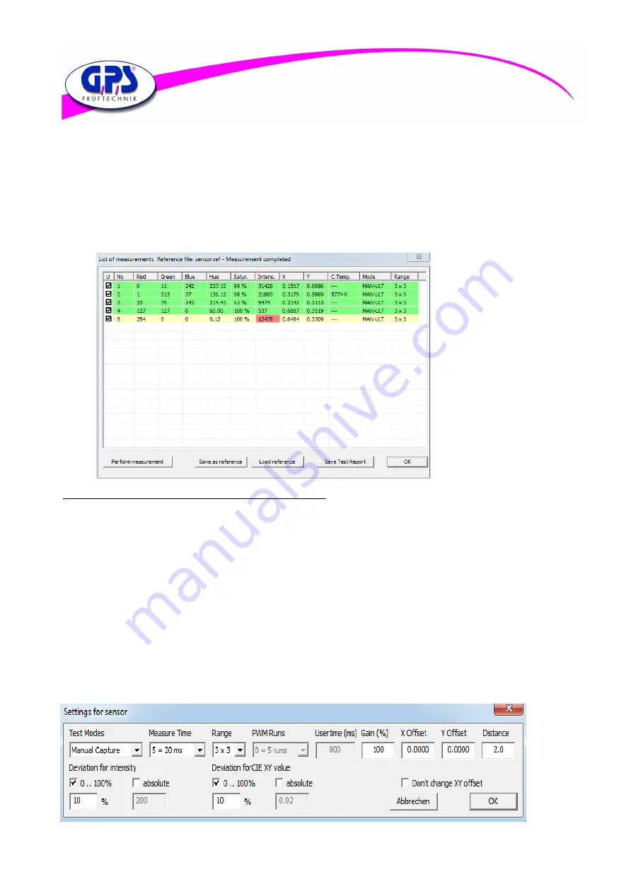
For that double click with the mouse in the “Measurement settings“ window on the wanted sensor line. The window
“Settings for sensor“ appears (see figure) .
Through this window tolerances referring to the intensity and the chromaticity coordinates XY can be entered. These
tolerances are provided by comparing the capture values with the reference values.
Furthermore any sensor settings referring to the test mode, the exposure time and the range can be modified during
Operation.
To enter an offset for the chromaticity coordinates XY you first have to deactivate the control box
“Don‘t allow any changes to XY values“ in the “Configuration“ window and confirm it by clicking the OK button.
Here too, modifications are taken over only at the nest measurement through the “Measurements“ window.
Figure 14.7: Comparing measurement
Figure 14.8: Settings for sensor