


02.11.2018
12
3.2 Setting an offset to calculate the tristimulus values x and y
There are three possibilities to store an offset for the calculation of the tristimulus values x and y.
These are explained in the following:
1.
GPS Prüftechnik offers a service for the calibration of the LED Analyzer Board. In this process customers
LEDs to be tested are measured with a proven calibrated spectrometer under a standardized process in
our company. In the next step tristimulus values which have been measured with the LED Analyzer are
adjusted to the values of the spectrometer. This takes place during uploading the firmware using a
non-volatile stored offset.
2.
In addition to that there is a possibility to integrate the LED Analyzer in an existing test system through
an initialisation of the com-port and a command listed in chapter 4. At this application an offset for each
LED that has to be measured can be stored using the commands “setx-0.xxxxb” or
“sety-0.xxxxb” . However this is a volatile stored offset which get lost after switching off the board
from the current source or after using the command “setdefaultb”.
3.
Furthermore an offset can be stored using the included software GPS LED Analyzer. This is, as
described in point 2, a volatile storage space and get lost after switched off from the current source or the
command “Reset board”. The following steps explain how an offset can be stored at the board using the
software.
Regarding to the LED Analyzer Software it has to be mentioned that stored offsets and modifications were
taken over and are shown in the menu displays “Measurement settings” or “Setting for sensor” only during
the measurement. See details for setting and adjusting an offset in chapter 3.3.4 .
Below you will find a brief explanation of an offset setting.
To set an offset through the LED Analyzer Software the ticker in the control box at “Don’t allow any
changes to the xy offset values” has to be removed. You find this control box under “Configuration” in
The PopUp-menu “Communication” In the next step you open “Measurement settings” under the PopUp-
Menu “Test” After opening all sensors, which are on the board , and their setting parameters are shown.
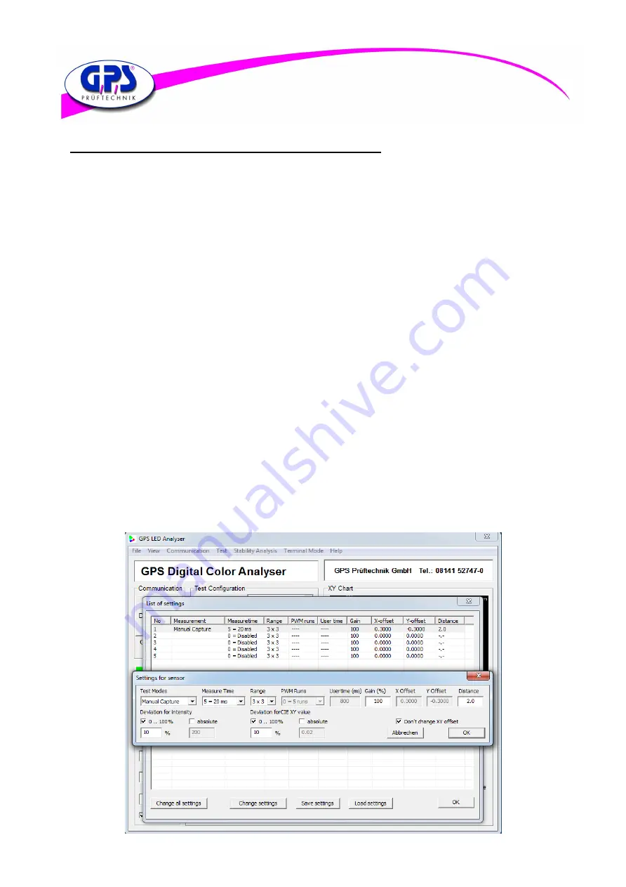
Now chose through double click on the line the wanted sensor to change the settings. Then the menu
display “Settings for sensor” appears (see figure below). To set an offset for the chromaticity coordinates
x and y it has to be guaranteed that the ticker in the control box “Don’t change x y offset” is removed.
After setting the wanted offsets close the “Settings for sensor” display through the OK-button.
Figure 13: Settings