GMS SERIES
OM-04386
PAGE E-11
MAINTENANCE AND REPAIR
HOUSING
ASSY
HEAD
CLEARANCE
CLEARANCE
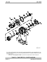
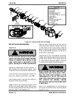
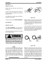
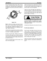
Figure E‐4.
End Clearance Adjustment
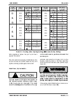
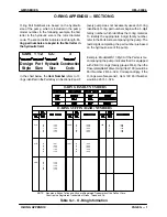
See Tables E-1 or E-2 to determine the gasket(s)
(01B) required for the viscosity and temperature of
the liquid being pumped. Remove the head from
the housing assembly and install the gasket(s).
Reinstall the head on the housing assembly (04)
and secure with the capscrews (B).
NOTE
The gasket set (01B) includes (2) 0.006 inch gas
kets and (2) 0.015 inch gaskets
and will accommo
date all standard clearances. If additional clear
ance is required, order two kits.
Notes:
For Special Applications, Consult Your Local
Gorman‐Rupp Distributor or the Factory.
Viscosities and Temperatures are Maximums.
Gasket Quantities Shown in Parenthesis.
Feeler Gauge
Reading
2500 SSU
225
_
F
(107
_
C)
0.000-0.002
0.003-0.006
0.007-0.010
(2) 0.015
250,000 SSU
300
_
F
(149
_
C)
(2) 0.015
(1) 0.006
(2) 0.015
(2) 0.006
(1) 0.015
(1) 0.006
(2) 0.015
(2) 0.015
(1) 0.006
Table E‐1.
End Clearance Gaskets
(Based on Liquid Viscosity)
35C, 35D, 35J, 35L &
35M
Rotor Trims
Feeler Gauge
Reading
Std
Rotor
Trims
0.000-0.002
0.003-0.006
0.007-0.010
0.011-0.014
0.015-0.018
(1) 0.015
(1) 0.006
(2) 0.015
(2) 0.015
(2) 0.015
(1) 0.006
(2) 0.015
(1) 0.006
(2) 0.015
(2) 0.006
Notes:
For Rotor Trim Codes Not Listed or for Special Applications,
Consult Your Local Gorman‐Rupp Distributor or the Factory.
Consult Pump Parts List For Rotor Trim Code.
(2) 0.015
(2) 0.006
(3) 0.015
(1) 0.006
(3) 0.015
(2) 0.006
(3) 0.015
(2) 0.006
Table E‐2.
End Clearance Gaskets
(Based on Rotor Trim Code)
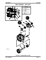
RELIEF VALVE DISASSEMBLY
(Figure E‐6)
NOTE
If the relief valve is low pressure, it will have one in
ternal spring (10AE). If the relief valve is high pres
sure, it will have two internal springs (10AE and
10AF).
Unscrew the cap (10AN) from the bonnet (10AK)
and remove the gasket (10AP). Back off the adjust
ment capscrew (10AM) to relieve pressure on the
spring(s) (10AE and/or 10AF).
Unscrew the bonnet from the valve body (10AA).
Remove the valve (10AD) and spring(s) (10AE and/
or 10AF). The spring guide (10AH) is an O‐ring fit in
the bonnet. Remove and discard the O‐rings.
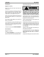
If the warning plate (10AB) must be replaced, re
move the drive screws (BM), and remove the plate.

