OM-04386
GMS SERIES
PAGE E-10
MAINTENANCE AND REPAIR
shaft and rotor must be replaced as an assembly.
Small scratches can be dressed with a fine file or
emery cloth. Replace the rotor/shaft assembly or
any other parts if wear or damage is extensive.
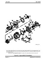
Carefully slide the rotor/shaft assembly into the
housing.
Use caution
not to scratch the I.D. of the
housing bushings (04B).
Head/Idler Kit (01/02)
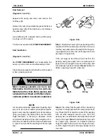
If the idler pin (01AB) was removed, apply Loctite
Pipe Sealant with Teflon No. 565 or equivalent com
pound to the I.D. of the idler pin bore in the head
(01A). Position the pin in the head with the cham
fered side toward the head and the milled flat side
facing the crescent. (If the pin is stepped, position it
with the large chamfered end toward the head.)
Use an arbor (or hydraulic) press to press the pin
into the head until it bottoms out.
NOTE
When properly installed, the pin will be positioned
0.010 inch below the surface of the crescent.
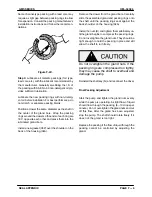
Lightly oil the I.D. of the idler (02A), and use an ar
bor (or hydraulic) press to install the idler bushing
(02B) in the idler. The bushing should be centered
at both ends of the idler.
Place the head (01A) on a flat surface. Lightly oil the
idler bushing (02B) and pin (01AB); install the idler
assembly (02) on the pin. Spin the idler to make
certain that it moves freely on the pin.
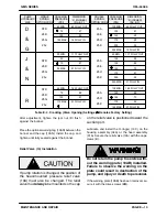
See
SETTING END CLEARANCE
and calculate
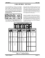
the number and thickness of gaskets (01B) re
quired for your application and hydraulic pump
size. Position the gasket(s) against the head, and
slide the head into the housing assembly. Rotate
the head (01A) until the groove in the head
matches the groove in the housing. Secure the
head to the housing with the capscrews (B).
Seal Installation (05)
The seal assembly (05) is available in a variety of
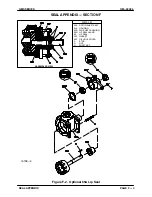
configurations. Check the
Parts List
furnished with
your pump to identify the seal, then refer to
Seal
Appendix,
Section F
, for installation of the seal
and related components.
Gland Installation (04N)
NOTE
The seal assembly (5) must be installed with the
gland. Check the
Parts List
furnished with your
pump to identify the seal, refer to
Seal Appendix
,
Section F
for installation of the seal and related
components, then proceed as follows with pump
reassembly.
Install the gland gasket (05P). With the seal and re
lated components installed, slide the gland (04N)
over the rotor shaft assembly (03A) and secure it to
the housing (or backhead) with the nuts (D).
Foot Bracket Kit (08, R Size Only
)
Secure the foot bracket (08A) to the head (01A)
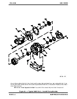
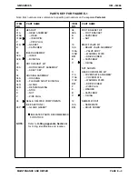
and backhead assembly (06A, Figure 2) with the
hardware (B and D).
SETTING END CLEARANCE
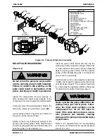
(Figures E‐1 and E‐4)
The end clearance between the head (01AA) and
the face of the rotor (03A) should be checked and
adjusted as required as part of a regular preventive
maintenance schedule, when performance drops
or the pump is disassembled.
NOTE
The end clearance is established
without
the head
gasket set (01B) in place.
Slide the head assembly into the housing assem
bly. Rotate the head (01AA) until the groove in the
head matches the groove in the housing. Secure
the head to the housing with the capscrews (B).
The head
must
be drawn completely tight against
the housing to establish the correct end clearance.
Use a feeler gauge to measure the clearance be
tween the front of the housing assembly and the
back of the head as shown in Figure E‐4.

