


8
SYSTEM EVACUATION
1.
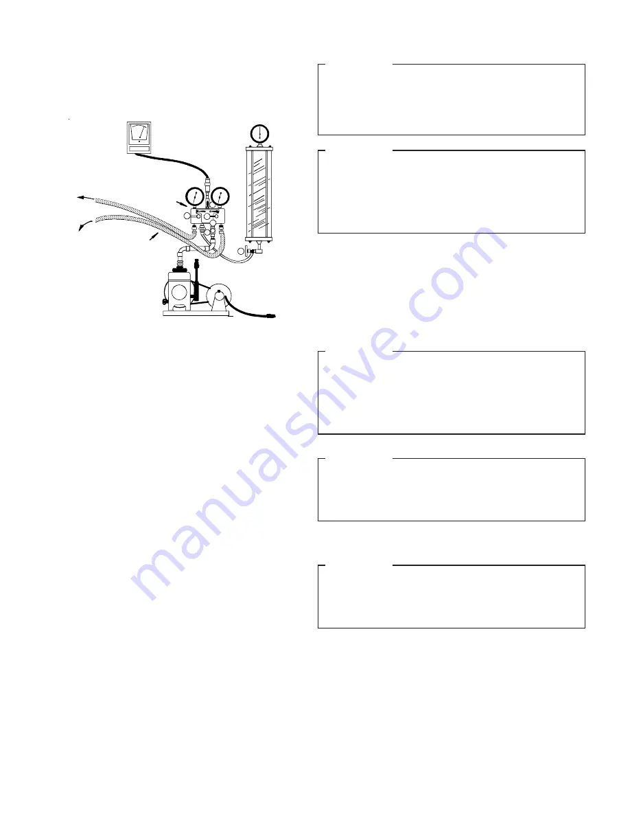
Connect the vacuum pump, high vacuum manifold set with
high vacuum hoses, thermocouple vacuum gauge and
charging cylinder as shown. Begin with all valves fully closed.
2.
If service dill valves are used for evacuation, use a core
remover to lift the valve core. It provides greater efficiency.
3.
Confirm proper pump and gauge operation. Open the shutoff
valve that leads to the high vacuum gauge manifold. Start
the pump. When the compound gauge (low side) reading
drops approximately 29 inches of vacuum, open the valve to
the thermocouple vacuum gauge and evacuate until the
gauge reads 250 microns or less.
4.
Close the valve to the thermocouple vacuum gauge. This
avoids potential gauge damage from “pegging the meter”.
5.
Open the high and low side valves on the gauge manifold.
Keeping the valve on the charging cylinder closed, open the
valve on the gauge manifold that leads to the cylinder.
6.
Evacuate the system to about 29 inches Hg as measured by
the compound (low side) gauge.
7.
Open the valve to the thermocouple vacuum gauge. Evacuate
until the gauge reads 250 microns or less.
8.
Close the valve to the vacuum pump. Wait five minutes, then
check the pressure on the thermocouple vacuum gauge:
¾
If the pressure is not more than 1500 microns, the system is
leak-free and properly evacuated. Proceed to Step 9.
¾
If the pressure rises, but holds at about 5000 microns,
moisture and non-condensibles are still present. Open the
valve to the vacuum pump, and go back to Step 7.
¾
If the pressure rises above 5000 microns, a leak is present.
Go back to “Leak Testing” section above
9.
Close the valve to the thermocouple vacuum gauge. Close
the valve to the vacuum pump. Shut off the pump.
A. LOW SIDE VALVE
B. HIGH SIDE VALVE
C. VACUUM PUMP
D. THERMOCOUPLE GAUGE
E. MANIFOLD GAUGE
F. CHARGING CYLINDER
C
A
B
E
D
HIGH VACUUM PUMP
LARGE DIAMETER
BRAIDED VACUUM
HOSES
TO
RELATED
GAUGE
PORTS OF
COND. UNIT
HIGH VACUUM
MANIFOLD
LOW SIDE
GAUGE
HIGH SIDE
GAUGE
DIAL-A-CHARGE
CHARGING CYLINDER
THERMOCOUPLE
VACUUM
GAUGE
F
PRELIMINARY CHARGE ADJUSTMENT
See the wiring diagram or outdoor unit specification sheet
to determine if this unit has a crankcase heater. If it does,
you must connect electrical power to the unit for four hours
before operating the compressor. Failure to do so could
result in compressor damage.
During all installation and service work, follow all regula-
tions of the Environmental Protection Agency. (This sys-
tem uses R-22 - an HCFC [Hydrogenated Chlorofluoro-
carbon].) It is a violation of EPA regulations to discharge
HCFC into the atmosphere and doing so may result in
fines or other penalties.
Use a male hex head wrench (5/16" for liquid) to carefully open
the liquid valve stem on the unit. Use a service wrench or cres-
cent wrench to open the suction ball valve. The valve is fully
open with a 90
°
turn (i.e. the stem is inline with the valve flow
direction).
The outdoor unit is factory charged with 2 lb. R-22.
IMPORTANT:
IMPORTANT:
IMPORTANT:
Use only refrigerant which is certified to meet ARI Stan-
dard 700. Used refrigerant may cause compressor dam-
age, and will void the warranty. (Most portable machines
cannot clean used refrigerant well enough to meet this ARI
Standard.)
IMPORTANT:
When adding additional refrigerant to a system, add only
refrigerant vapor (not liquid) through the suction valve (low
side) on the outdoor unit. Any other practice may cause com-
pressor damage.
FINAL CHARGE ADJUSTMENT
IMPORTANT:
Never operate the compressor with the suction valve closed
to “test the compressor’s pumping efficiency”. In some cases,
this can result in serious compressor damage and loss of
warranty coverage.
For 25’ of line set the 7-1/2 ton charge is approximately 19 lb.
For 25’ of line set the 10-ton is approximately 26 lb. of R-22.
DO
NOT start
with these amounts
.
Figure 11.