


10
During defrost the following actions occur:
1.
The reversing valve is energized and the heat pump
operates in the cooling mode.
2.
The airhandler auxiliary heat (if equipped) is activated.
3.
The condenser fan motor is shut-off.
If the defrost cycle has not terminated after ten (10) minutes the
control will override the defrost sensor and revert to a heating
mode.
The defrost control has test pins which can be useful when trouble-
shooting in the heating mode. These test pins accelerate the com-
pressor run time counter. The suggested method for accessing
this feature is:
A. Run unit in heat mode.
B. Check unit for proper charge.
Note:
Bands of frost indicate low refrigerant charge.
C. Shut off power to unit.
D. Disconnect outdoor fan by removing the purple lead from
the Condenser Fan Defrost Relay.
E. Restart unit and allow frost to accumulate.
F. After a few minutes the defrost thermostat should close.
To verify the position of the thermostat check for 24V
between “DFT” and “C” on the defrost board. Should the
defrost thermostat fail to close after a heavy build-up of
frost and the thermostat is less than 28
°
, the thermostat is
to be replaced.
G. After the thermostat has closed, short across the test pins
with the a screwdriver blade until the reversing valve
shifts. This could take up to 21 seconds depending upon
the position of the timing setting on the defrost board.
Immediately upon the action of the reversing valve,
remove the short.
Note:
If this short is not removed
immediately, the defrost activity will last only 2.3 seconds.
H. After defrost has terminated (up to 10 minutes) check the
defrost thermostat for 24V between “DFT” and “C”. This
reading should be 0 V (open sensor).
I. Shut off power to the unit.
J. Replace outdoor fan motor wire removed in Step D.
XV TROUBLE SHOOTING
QUALIFIED INSTALLER/SERVICER ONLY
When troubleshooting, the first step should always be to check
for clean coils, clean filter(s), and proper airflow. Indoor airflow
should be 375 to 425 CFM per ton of cooling based on the size of
the outdoor unit. The most common way of establishing indoor
airflow is heating temperature rise. Indoor airflow will then be
(Heating output of equipment) / (1.1 x temp. rise). In other cases,
measurement of external static pressure is helpful. For details,
see the Installation Operator Instructions for your indoor
equipment.
3 Phase Scroll Compressor
The CPLE090/120 condenser is equipped with a 3-phase
scroll compressor. If the unit sounds noisy and/or the suction
and liquid pressures are almost equal, the compressor is
operating in the reverse rotation. Reverse (2) incoming
power supply leads.
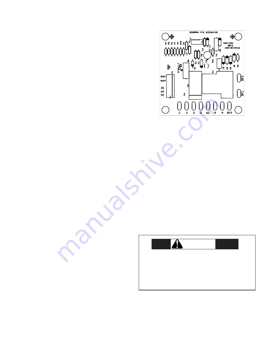
CAUTION
SHUNT
SELECTION
JUMPER
Figure 12.