1
INSTALLATION & OPERATING INSTRUCTIONS
7-1/2 & 10 TON
SPLIT SYSTEM HEAT PUMP
12/02
IO-229
GOODMAN MANUFACTURING COMPANY, L.P.
2550 North Loop West, Suite 400
Houston, Texas 77092
www.goodmanmfg.com
Page 1: ...1 INSTALLATION OPERATING INSTRUCTIONS 7 1 2 10 TON SPLIT SYSTEM HEAT PUMP 12 02 IO 229 GOODMAN MANUFACTURING COMPANY L P 2550 North Loop West Suite 400 Houston Texas 77092 www goodmanmfg com...
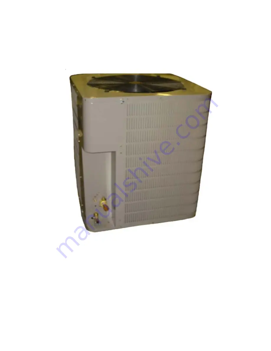
Page 2: ...0 10 Tons Series Identification CPLE Louvered Series Heat Pump WARNING III Product Description When matched with the appropriate airhandler s or evaporator coil s the CPLE090 120 heat pump complies wi...
Page 3: ...and obstruc tions such as walls or overhangs Note It is recommended that adequate service clearances also be considered Refrigerant System Requirements The selected site should be no greater than 50 b...
Page 4: ...refrigerant leaks Post Brazing Quench all welded joints with water or a wet rag Corner CPLE090 CPLE120 A 95 Lbs 110 Lbs B 95 Lbs 110 Lbs C 80 Lbs 85 Lbs D 95 Lbs 110 Lbs Arrange the straps to form a c...
Page 5: ...in accordance with the Canadian Electric Code CSA C22 1 Failure to observe this warning can result in electrical shock that can cause serious personal injury or death WARNING 220 216 4 100 x 4 216 400...
Page 6: ...the unit Refer to the latest edition of the National Electric Code or in Canada the Canadian Electric Code when determining the correct wire size The following table shows the current carrying capabi...
Page 7: ...found repair them After repair repeat the above pressure test If no leaks exist proceed to system evacuation WARNING WARNING Leak Testing To avoid possible explosion the line from the nitrogen cylinde...
Page 8: ...YLINDER C A B E D HIGH VACUUM PUMP LARGE DIAMETER BRAIDED VACUUM HOSES TO RELATED GAUGE PORTS OF COND UNIT HIGH VACUUM MANIFOLD LOW SIDE GAUGE HIGH SIDE GAUGE DIAL A CHARGE CHARGING CYLINDER THERMOCOU...
Page 9: ...oil to run down to the inner cap seal surface Close caps finger tight Then tighten cap additional two to three hex flats System Charging Heating Mode The following method can be employed as a method...
Page 10: ...driver blade until the reversing valve shifts This could take up to 21 seconds depending upon the position of the timing setting on the defrost board Immediately upon the action of the reversing valve...
Page 11: ...ect switch open 2 Blow fuse or fuse at disconnect switch 3 Thermostat set too high 4 Selector switch in Off position 5 Contactor and or relay coils burned out 6 Loose or open electrical connection in...
Page 12: ...ving to operate We use the highest quality materials and components available because if a part fails then the unit fails Finally every unit is run tested before it leaves the factory That s why we kn...