background image

5000 Series User’s Manual

5-60 

GEK-99044

Hex Print

This menu option is used to enable/disable the Hex Print option. This
is used to troubleshoot communications or applications program
problems. The received EBCDIC data stream is converted to hex
dump format and printed. The printout can aid in determining what

the printer is being instructed to do by the data stream.

Use the following procedure to enable/disable a setting:

1.


While in the 

IBM Format

 menu, press the 

 (left) or 

 (right)

menu browse pushbutton until 

Hex Print

 is displayed in the lower

right corner of the LCD.

2.


Press the 

 (down) menu browse pushbutton to access the 

Hex

Print

 options.

3.


Press the 

 (left) or 

 (right) menu browse pushbutton until the

desired option is displayed. Press the 

Select

 pushbutton to enable

or disable an option. The < symbol will immediately follow an
enabled option.

Hex 1

This menu option is used to select the HEX 1 setting for IBM Format.
This is a user set option. Hex 1 defines the first character (in
EBCDIC) of the lead-in sequence for hex passthru. Hex passthru

enables sending commands in the datastream to access features that
are not available in standard IBM emulations. Hex passthru requires
an identification of two lead-in characters (Hex 1 and Hex 2)
indicating the beginning of the command stream and a terminating
character (Hex Term) indicating the end of the command stream.

Upon receipt of the two lead-in characters, the emulation controller
begins translating the EBCDIC characters 0 to 9 and A to F into
hexadecimal data. Two EBCDIC characters are combined into one
ASCII hexadecimal byte and sent to the printer. Translation
continues until the emulation controller receives the terminating
character.

Use the following procedure to select this option:

1.


While in the 

IBM Format

 menu, press the 

 (left) or 

 (right)

menu browse pushbutton until 

HEX 1

 is displayed in the lower

right corner of the LCD.

2.


Press the 

Select

 pushbutton to configure the 

HEX 1

 options.

3.


Notice the cursor (underline) is now shown under the first digit.
The horizontal 


 (left or right) menu browse pushbuttons to

position the cursor (underline) under the digit to be changed; the
vertical 


 (up or down) menu browse pushbutton

increment/decrement the selected numeric digit by one.

4.


Press the 

Clear

 pushbutton 

after

 all changes are complete 

and

the desired value is displayed in the lower right corner of the
LCD.

Note

Repeat this section if further changes are necessary.

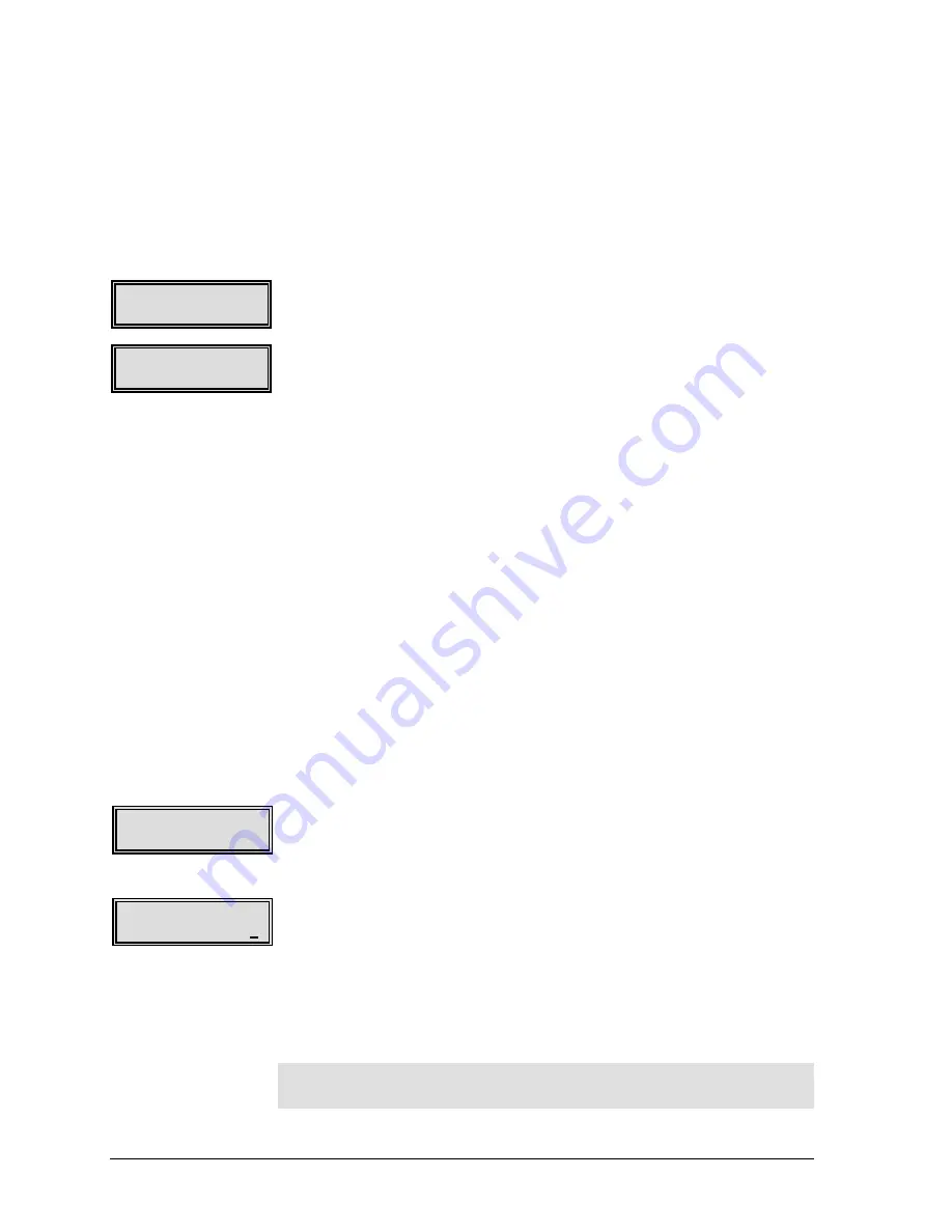
IBM Format

HEX 1

HEX 1

00

IBM Format

Hex Print

Hex Print

Disable

Summary of Contents for 5050

Page 1: ...GEK 99043 GENICOMConfidential Duplication Prohibited Without Written Authorization GEK 99032 Models 5050 5100 5180 User s Manual g e n i c o m Line Printers ...

Page 2: ...is connected Consult the dealer or an experienced radio TV technician for help FCC warning Changes or modifications not expressly approved by the party responsible for compliance could void the user s authority to operate the equipment Note the following The use of a non shielded interface cable with the referenced device is prohibited The length of the parallel interface cable must be 3 meters 10...

Page 3: ... Token ring IBM TX CX Schnittstellenkarten oder eine variation der herkoemmlicken Parallelscnittstellenkarten interface in einer oder beiden steckbaren Erweiterungsschnittstellen installiert sind koennen moeglicherweise zusaetzliche Funkfrequenzstoerungen erzeugt werden unter Einhaltung der EN55022 Klasse A Stoerstrahlungswerte ENERGY STAR As an ENERGY STAR Partner GENICOM has determined that this...

Page 4: ...ICOM Corporation The following companies own the other trademarks used in this manual GENICOM Corporation Centronics International Business Machines Corporation IBM Epson Corporation Epson All other product names mentioned in this manual may also be trademarks of their respective companies ...

Page 5: ...ng the power cord connected may damage the printer or other property Do not put the printer in direct sunlight near a heater or near water Leave adequate space around the printer Use only a shielded interface cable 3 meters 10 feet or less for the parallel interface 15 meters 50 feet or less for the serial interface 100 meters 328 feet or less for Ethernet interface 10Base T connection and 185 met...

Page 6: ...ta Entry 2 6 INSTALLING THE PAPER HANDLING SYSTEM 2 8 55 OR 60 DBA CABINET MODELS 2 8 Paper Handling Aids 55 dBa Cabinet Models 2 11 SELECTING THE PAPER PATH 2 11 5050 5100 55 AND 60 DBA CABINET MODEL ONLY 2 11 Wire Paper Guide 2 12 LOADING PAPER 2 14 Manual Paper Loading 2 14 Semiautomatic Paper Loading 2 18 HORIZONTAL POSITIONING OF THE PAPER 2 19 THE RIBBON DECK 2 20 5050 5100 55 OR 60 DBA CABI...

Page 7: ...2 Setup Menu 3 2 Maintenance Menu 3 2 Menu Control 3 3 SETTING UP A FORMAT 3 3 Active Format 3 3 Setting up an Active Format 3 4 Form Length 3 4 Top Margin 3 4 Bottom Margin 3 4 Top Print Ref 3 4 Explanation of the Top Print Ref 3 5 Example 3 5 LOW PAPER PRINTING 3 7 Low Paper 3 7 Replenishing Paper Supply 3 7 SETTING TOP OF FORM 3 8 PAPER TEAR OFF FEATURE 3 9 Paper Path 5050 5100 55 or 60 dBa Cab...

Page 8: ...at 5 2 Format Name 5 2 Font Style 5 2 CharSet Country 5 3 Character Set 5 3 Country 5 3 CPI 5 4 LPI 5 4 Form Length 5 5 Top Margin 5 5 Bottom Margin 5 6 Left Margin 5 6 Right Margin 5 7 Top Print Ref 5 8 Left Print Ref 5 9 Horiz Expansion 5 9 Vert Expansion 5 10 VertExp Options 5 10 Print Modifiers 5 11 Print Options 5 11 Slew Rate 5 12 Save Format 5 12 HORIZ TAB 5 13 VERTICAL FORMAT 5 13 Vertical...

Page 9: ... 29 TCP IP 5 30 Netware 5 30 ENGINE OPTIONS 5 31 Direction 5 31 EngineOff Delay 5 31 Print Intensity 5 32 PRINT CONTROL 5 32 Define LF 5 33 Define CR 5 33 Define FF 5 33 Define HT 5 34 VertMove 5 34 AutoWrap 5 34 FF TOF 5 35 GenPtrOpts 5 35 TEAROFF 5 35 Path 5 36 Retract 5 36 Auto 5 36 EMULATION 5 37 ANSI 4800 5 38 ANSI 4410 5 38 FX286E 5 39 ProPrinter 5 39 P 300 600 5 40 DEC LG 5 40 Pseries 5 41 ...

Page 10: ... IPDS BC Stagger 5 54 IPDS BC Density 5 55 IPDS GR Density 5 55 IPDS Image Density 5 55 IPDS Dens Ovr 5 56 IBM Format 5 56 Code Page 5 56 Code Pg Override 5 57 LPI Override 5 57 CPI Override 5 57 MPP Override 5 58 MPL Override 5 58 Override Text 5 59 Override All 5 59 Hex Print 5 60 Hex 1 5 60 Hex 2 5 61 Hex Term 5 61 DCF1 5 61 DCF2 5 62 DCF Term 5 63 Coax Compat 5 63 Case 5 64 LOC Copy FF 5 64 FF...

Page 11: ...ctrical Problems 7 10 Mechanical Problems 7 11 Self test Error Messages 7 12 SERIAL INTERFACE ERRORS 7 13 PRINT HEAD REPLACEMENT 7 13 5050 5100 50 55 OR 60 DBA CABINET MODEL 7 13 Replacement Procedure 7 14 PRINT HEAD REPLACEMENT 7 18 5180 52 OR 55 DBA CABINET MODEL 7 18 Resetting Print Head Counters 7 21 APPENDIX A UNPACKING INSTRUCTIONS A 1 UNPACKING 5180 52 DBA MODEL A 1 Unpacking 5050 5100 55 D...

Page 12: ...D 2 E 3 CANADIAN PST E 3 APPENDIX F FLASH UPGRADE INSTRUCTIONS F 1 APPENDIX G DESCRIPTION OF STRAPPING OPTIONS G 1 LEGACY PARALLEL HARDWARE STRAP DEFINITIONS G 2 LEGACY PARALLEL SOFTWARE STRAP DEFINITIONS G 3 GENERAL PRINTER OPTIONS DEFINITIONS G 4 EMULATION OPTION DESCRIPTIONS G 6 APPENDIX H H 1 INTERFACE EMULATION COMPATIBILITY G 1 APPENDIX I LCD MENU MAPS I 1 ...

Page 13: ...r exit standard 5050 5100 55 or 60 dBa Cabinet Model Industrial graphics bar codes and labels Other characteristics include Input voltage 5050 5100 Models auto range selecting 115V or 230V 5180 Models switchable 115V or 230V Hardware interfaces menu selectable or auto switching between CENTRONICS parallel and RS 232 serial Standard emulation s menu or host selectable ANSI 4800 ANSI 4410 Epson FX28...

Page 14: ...abinet specific The differences are noted within sections where possible and separated into section where necessary The following is a visual representation of the cabinet models available This User s Manual is divided into the following main sections Chapter 1 Introduction This chapter contains a brief introduction to the key features of the printer and the organization of this manual Chapter 2 G...

Page 15: ...cking This appendix contains information necessary to unpack the printer or repack the printer for shipment Appendix B Paper Considerations This appendix contains information as a guide to paper supplies Appendix C Considerations for Operation This appendix contains specifications on the printer Appendix D Parts Accessories Consumables Options This appendix contains a list of available parts acces...

Page 16: ... chapter in the order presented CONNECTING THE POWER CORD The 5050 5100 50 55 or 60 dBa Cabinet Model printer is equipped with an auto switching power supply and can be connected to either a 115V or 230V source without damage or manually changing a switch setting The 5180 52 or 55 dBa Cabinet Model has a voltage selection switch located on the back panel The switch has two positions 115V and 230V ...

Page 17: ...NNECTING THE INTERFACE CABLE Both a 25 pin RS 232C serial interface connector and a 36 pin CENTRONICS parallel interface connector are standard on this printer Both connectors are located on the data connector plate on the rear of the printer See Figure 2 2 FIGURE 2 2 REAR VIEW OF PRINTER 5050 5100 55 dBa MODEL POWER ON OFF I O SWITCH POWER CORD RECESSED CONNECTOR I O CARD INTERFACE SLOTS 25 PIN S...

Page 18: ...T and Token Ring DESCRIPTION OF THE CONTROL PANEL The control panel is mounted in the top of the printer and is accessible with the top cover either open or closed The Control Panel utilizes a display panel composed of two rows of sixteen characters each With the top cover open the control panel will move around slightly to the touch This is normal The floating mount allows the panel to align itse...

Page 19: ...80 55 dBa Cabinet Model are different however the functionality of each is the same When in the online state only the FF On Line Off Line Tear Off View pushbuttons and limited functionality of the Clear and Select pushbuttons are active Pressing any other pushbutton causes a beep The Processing LED indicator is lit whenever data is being received and or being processed printed In multi source I O ...

Page 20: ...s access to the menu functions Pressing the pushbutton moves paper up incrementally Pressing the pushbutton moves paper down incrementally Pressing the TOF Top of Form pushbutton sets the top of form position on the printer Pressing the Format pushbutton allows the operator to select from up to ten stored formats The pushbutton is repeatedly pressed until the desired set up format is being display...

Page 21: ...Pressing the up or down menu browse pushbuttons allows navigation up or down a level of menus While in a user set option these pushbuttons are used for data entry Data Entry There are two modes of data entry for the control panel The first mode is to select from a list of several options displayed on the bottom line of the LCD The entries are sequentially displayed on the bottom line of the LCD in...

Page 22: ...ue Depressing the up menu browse pushbutton increments that digit from 12 0 to 22 0 or higher where only the first digit increments Depressing the right arrow pushbutton moves the cursor from 22 0 to 22 0 Depressing the right arrow again moved the cursor from 22 0 to the 10th position the decimal point is automatically skipped over from 22 0 to 22 0 Depressing the right down arrow pushbutton chang...

Page 23: ...s shaped differently but its functionality is the same see Figure 2 4b The 5050 5100 50 dBa and 5180 55 dBa Cabinet Models have internally installed paper handling aids WICKETS PAPER SHELF V SHAPED STACKING AID FIGURE 2 4A PAPER HANDLING SYSTEM 5050 5100 55dba TIGHTENING KNOB PAPER SHELF WIRE UPPER PAPER RACK 5050 5100 55 dBa Model FIGURE 2 4b UPPER RACK AND LOWER PAPER SHELF INSTALLED 5180 55 dBa...

Page 24: ...ghtening knobs are facing away from the area the paper will occupy 3 Slide the wickets along the shelf so the distance between the wickets accommodates the length of the fanfold paper form length 4 Lay the V shaped paper stacking aid on the shelf between the wickets This stacking aid should be used when stacks of 1000 or more forms are anticipated See Figure 2 4a and Figure 2 4b 5 Hook the paper r...

Page 25: ...n the left and connect the two static ground wires See Figure 2 6a FIGURE 2 6a SIDE VIEWS 5050 5100 55 dBa CABINET MODEL STATIC GROUND WIRE CONNECTOR TWO PLACES FINISHED INSTALLATION ATTACH GROUND CABLES METAL HOOK HANGS ON EDGE OF OPENING FIGURE 2 6b REAR VIEW 5180 55 dBa CABINET MODEL FINISHED INSTALLATION SWING RACK UP ...

Page 26: ...ling device shipped with the printer is a V shaped metal paper stacking aid Some papers tend to curl as the stack builds in the paper compartment This device will alleviate that situation See Figure 2 8 SELECTING THE PAPER PATH 5050 5100 55 and 60 dBa CABINET MODEL ONLY This printer has a top exit paper path and a rear exit paper path The top path is used when forms or peel off labels are printed ...

Page 27: ...to use either path Wire Paper Guide The printer is shipped with a wire paper guide installed The purpose of this part is to prevent paper jams when the rear default paper exit is used To thread paper through the rear exit lift up the paper guide until it sticks to the magnet on the top cover See Figure 2 10 FIGURE 2 10 WIRE PAPER GUIDE 5050 5100 55 OR 60 dBa CABINET MODEL PAPER GUIDE MAGNET FIGURE...

Page 28: ... 11b and 2 11c If the rear exit paper path is used without the paper guide installed paper may jam in the top cover To re install the paper guide find the wires that are closest together on the left end Install the guide so that these two wires straddle the left mounting bracket This holds the part in place horizontally The small ring on the paper guide slides onto the corresponding prong on the p...

Page 29: ...id the printer warranty Full width paper greater than 14 5 8 inch or 371cm should be used until the operator is familiar with the printer s setup and operation Manual Paper Loading To load paper in the printer complete the following steps 1 Raise the top cover to the open position On 5050 5100 55 or 60 dBa Cabinet Model printers press the cover latch to unlock the cover See Figure 2 13 Paper Out F...

Page 30: ...er the fault messages Paper Out and Strikr Bar Open will appear on the display panel and the beeper will sound These will alternately display in the upper left corner of the display panel until the CLEAR pushbutton is pressed 3 Push the paper tension adjustment lever down to position 1 See Figure 2 14a b Strikr Bar Open FIGURE 2 14a PRINT GAP WHEEL IN LOAD POSITION 5050 5100 50 55 or 60 dBa CABINE...

Page 31: ...s it leaves the box 6 On 5050 5100 55 or 60 dBa Cabinet Model printers grasp the bottom edge of the front access panel of the printer and lift it to the open position A magnetic latch will hold the panel open See Figure 2 16 FIGURE 2 15 TOP VIEW OF PRINTER 5050 5100 55 dBa CABINET MODEL SHOWN UPPER LEFT TRACTOR UPPER RIGHT TRACTOR LOWER TRACTOR DOORS FIGURE 2 16 FRONT ACCESS PANEL AND FRONT CABINE...

Page 32: ...rinter a minimum of 4 inches see Setting Top of Form Later vertical positioning and top of form TOF alignment will be completed after the printer is in operation 9 Place the paper onto the pins of the upper left tractor and close the tractor door If necessary release the locking lever on the right hand tractor by flipping it down and slide the tractor sideways to match the paper width If necessary...

Page 33: ...d power has been applied the semiautomatic paper loading feature may be used After the paper is loaded in the lower tractors pressing the FF form feed pushbutton causes the paper to move up at a slower rate 10 inches per second to the top tractors Note Some extremely thin forms stiff cardstock forms with raised labels or envelopes with cutouts may not work with this feature If there are problems l...

Page 34: ...ted on the left just above the paper gap wheel See Figure 2 26 If a left margin is desired it is set electronically through either the control panel pushbuttons or a command sent by the host The marks on the label are set up for paper with a 1 2 inch perforation strip Aligning the edge of the paper with the first mark as shown below will cause the first column to print immediately after the perfor...

Page 35: ... deck as the cartridge is lowered onto the deck When the locking lever is moved to the RUN position the drive gears move together to grip the fabric See Figure 2 20 After the ribbon cartridge is in place and the locking lever has been turned to the RUN position the ribbon drive knob is turned clockwise to manually advance the ribbon fabric DRIVE GEARS SEPARATED OPEN LOCKING LEVER IN LOAD POSITION ...

Page 36: ...tioning pin located to the left of the air duct and behind the captive screw Also located on the ribbon deck is the print module access panel See Figure 20b CAPTIVE SCREW PRINT MODULE ACCESS PANEL DRIVE MECHANISM FOR RIBBON CARTRIDGE CAPTIVE SCREW PART OF AIR DUCT FOR PRINT MODULES FIGURE 20b THE RIBBON DECK 5180 52 OR 55 dBa CABINET MODEL POSITIONING PIN LOCATED HERE ...

Page 37: ...ion See Figure 2 21 RIBBON REMOVAL AND INSTALLATION 5050 5100 50 55 OR 60 dBa CABINET MODEL 1 Raise the top cover On the 5050 5100 55 or 60 dBa model printers press the cover latch to unlock the cover 2 Turn the print gap wheel to the LOAD position 3 Turn the ribbon locking lever clockwise to the LOAD position 4 Make sure the orange slide lever on the ribbon cartridge is in the full left position ...

Page 38: ...t to back matches the tilt of the ribbon deck See Figure 2 22 7 Lower the ribbon cartridge onto the ribbon deck so that the drive gears on the deck enter the opening on the bottom of the cartridge 8 After the cartridge is in place grasp the ribbon shipping tab on the ribbon cartridge and pull it up and towards the left to remove it from the cartridge FIGURE 2 22 LEFT SIDE CUTAWAY VIEW RIBBON CARTR...

Page 39: ...necessary turn the yellow spool knob to straighten the fabric See Figure 2 23 FIGURE 2 23 CHANGING OR REINSTALLING A RIBBON ORANGE SLIDE LEVER WINDOW YELLOW SPOOL KNOB RIBBON FABRIC FABRIC RELATIVELY STRAIGHT FABRIC TOO LOOSE FABRIC BETWEEN GEARS FABRIC SNAGGED ON GEAR LOOKING THROUGH THE WINDOW WITH THE CARTRIDGE OFF THE DECK LOOKING THROUGH THE WINDOW WITH THE CARTRIDGE ON THE DECK ...

Page 40: ...s chapter for more information Removing a Ribbon 50 55 or 60 dBa Cabinet Model 1 Place the printer offline and raise the top cover 2 Turn the print gap wheel to the LOAD position If necessary see Figure 2 14 3 Turn the ribbon locking lever clockwise to the LOAD position If necessary see Figure 2 24 4 Lift the ribbon off the ribbon deck RIBBON REMOVAL AND INSTALLATION 5180 52 OR 55 dBa CABINET MODE...

Page 41: ...ld Then lower the right side of the cartridge onto the ribbon motor drive shaft Turn the knurled knob on the ribbon cartridge to allow the drive shaft to enter the cartridge Turn the knob a few more times to assure that the ribbon is running freely and that any remaining slack is removed REINKER PIN FIGURE 2 25 RIBBON CARTRIDGE 5180 52 or55 dBa CABINET MODEL BOTTOM TOP KNURLED KNOB FOR TIGHTENING ...

Page 42: ...use unacceptable print quality and excessive noise Note The moisture and content and the thickness of the paper determine the ideal setting Adjust the print gap wheel to produce the best quality possible Reading the Scale The print gap wheel on the 5050 5100 55 or 60 dBa Cabinet Model has two scales to aid in setting the proper gap See Figure 2 27 Using the White Scale The white scale with the bla...

Page 43: ...STMENT The paper tension lever is located next to the print gap wheel It is used to maintain the proper tension on the paper during printing See Figure 2 28 On the 5180 55 dBa Cabinet Model the paper tension lever is located to the left of the print gap adjust knob See Figure 2 30 Move the lever to position 1 the bottom position when loading paper setting top of form and printing single part paper...

Page 44: ... software and Loading is displayed in the upper left corner of the display and Please wait is displayed in the lower right corner of the display The printer s display briefly shows Self Test before returning to the previous display During this loading and self test phase the alarm light flashes 3 The printer completes the sequence in approximately 15 seconds 4 When the power on sequence and self t...

Page 45: ...n the print area are accessible The ribbon deck must be in place and all three thumbscrews must be tightened securely for printer operation See Figure 2 29 Note Removing the ribbon deck with the power applied will energize the interlock circuit If this happens the deck must be replaced power must be turned off for a period of 5 minutes before attempting to reapply power THREE THUMBSCREWS FIGURE 2 ...

Page 46: ... interlock switch Print Module Access Panel AC Interlock Switch The AC interlock switch disconnects AC power from the power supply when the print module access panel is lifted See Figure 2 30 This eliminates any potential shock hazard or inadvertent printer start up while moving parts in the print area are accessible The shelf must be in place and the screws must be tightened securely for printer ...

Page 47: ...to those used before initialization See Show in the Using the Operator s Menu section of Chapter 4 for procedures to print the status page and formats page Note The menu option All Formats will reset all previously saved formats customer defined to factory defaults Previously saved formats cannot be recalled It is recommended a status page and format page be printed before performing this option U...

Page 48: ...omplete a power up sequence TEST PATTERN PRINTING 1 With the printer in Local menu press the down menu browse pushbutton to access the main menu options 2 Press the left or right menu browse pushbutton until Operator is displayed in the lower right corner of the display window 3 Press the down menu browse pushbutton to access the Operator menu options 4 Press the left or right menu browse pushbutt...

Page 49: ...e backward up to a previous level of selections 10 Press the On Line pushbutton again This will return the printer to an online status If printing becomes lighter gradually over a period of time the ribbon may need replacing See Figure 2 28 below for the print pattern sample using the default settings FIGURE 2 31 PRINT PATTERN SAMPLE ...

Page 50: ... menu functions This state is also referred to as Local Fault The fault state is a special case where a few options are available as the machine is in a condition that may inhibit many operations It will allow operations that are required to clear the fault condition s The normal exit when a fault is corrected is to depress the Clear pushbutton Menu The menu state is where the settings or configur...

Page 51: ... the printer as the type of print job changes Normally the Operator menu involves loading paper correcting faults and allows temporary changes to settings that have previously been selected in the Setup menu If the selection desired is not available in the Operator menu proceed to the Setup menu For procedures to navigate the operator menu see Chapter 4 For a complete listing of menu selections se...

Page 52: ... print ref horizontal expansion vertical expansion vertical expansion options printing modifiers print options and slew rate Although the entire length of the form is available for printing some combination of a top and bottom margin or a bottom margin and offset is recommended to avoid printing on the paper perforation and possibly snagging print wires NOTE Up to ten stored set up configurations ...

Page 53: ...argin The top margin is set using the currently set lpi value If the top margin is set to 6 lines while the lpi is set to 6 printing will start on line 7 Lines 1 6 1 inch will be skipped After the form has been set up a lpi change will not alter the length of the margin Bottom Margin The bottom margin is set using the currently set lpi value If the bottom margin is set to 57 lines while the lpi is...

Page 54: ...l move commands line feed form feed etc This will continue through the box of forms to be printed The Top Print Ref is used to position the string of forms to the first print line on the first form The host is then responsible for advancing the paper to the next form s first print line with form feed commands Example To print standard data listings the operator selects an 11 inch form at 6 lpi wit...

Page 55: ...print job is finished Papers in both examples were loaded with the perforation at the alignment pointers of the upper tractors Without the offset Example A the data printed starts at the first printable line of the form The paper should have been loaded with the perforation 1 inch above the pointers for the desired results Example B shows the effect of the special offset top print ref on the print...

Page 56: ...r line of the display window 2 Press the On Line pushbutton and the printer will finish the remainder of the current form and stop Local will be displayed in the upper line of the display window and Low Paper Status will be displayed in the lower line of the display The printer will finish the remainder of the current form and stop 3 The alarm light will flash and Paper Out will display in the upp...

Page 57: ... set the top of form 1 The paper perforation must first be positioned at the pointer on each of the upper tractor doors See Figure 3 1 2 Position the paper using the pushbutton and or pushbuttons if necessary 3 Press the TOF pushbutton After the perforation is positioned at the pointers and the TOF pushbutton is pressed the printer will move the paper so that the paper is correctly positioned at t...

Page 58: ...ndition such as Ribbon Jam or Strikr Bar Open Paper Path 5050 5100 55 or 60 dBa Cabinet Model Only The distance the forms are ejected and retracted depends on which paper path top exit or rear exit is being used See TearOff menu option in chapter 5 Number of Forms Ejected This feature works by performing a series of forward form feeds to eject the paper and a shorter series of reverse form feeds t...

Page 59: ...M LENGTH INCHES NUMBER OF FORMS EJECTED NUMBER OF FORMS RETRACTED INCHES RETRACTED 0 5 34 22 11 1 0 17 11 11 1 5 12 8 12 2 0 9 6 12 2 5 7 4 10 3 0 6 4 12 3 5 5 3 10 5 4 0 5 3 12 4 5 4 2 9 5 0 4 2 10 5 5 4 2 11 6 0 3 2 12 6 5 3 2 13 7 0 3 2 14 7 5 3 2 15 8 0 3 2 16 8 5 2 1 8 5 9 0 2 1 9 9 5 2 1 9 5 10 0 2 1 10 10 5 2 1 10 5 11 0 2 1 11 11 5 2 1 11 5 12 0 2 1 12 12 5 2 1 12 5 13 0 2 1 13 13 5 2 1 13...

Page 60: ...8 2 5 1 6 0 1 8 2 1 6 5 1 8 1 5 1 7 0 1 8 1 1 7 5 1 8 5 1 8 0 1 8 0 1 8 5 1 8 5 5 1 9 0 1 9 1 1 9 5 1 9 5 1 5 1 10 0 1 10 2 1 10 5 1 10 5 2 5 1 11 0 1 11 3 1 11 5 1 11 5 3 5 1 12 0 1 12 4 1 12 5 1 12 5 4 5 1 13 0 1 13 5 1 13 5 1 13 5 5 5 1 14 0 1 14 6 1 14 5 1 14 5 6 5 1 15 0 1 15 7 1 15 5 1 15 5 7 5 1 16 0 1 16 8 1 16 5 1 16 5 8 5 1 17 0 1 17 9 1 17 5 1 17 5 9 5 1 18 0 1 18 10 1 18 5 1 18 5 10 5 ...

Page 61: ... depress the FF pushbutton and the pushbutton while turning the power on to the printer The printer will power up as normal Note Keep the FF pushbutton and pushbutton depressed until the power up sequence is complete 1 Press the On Line pushbutton to place the printer in a Local offline status 2 Press the down menu browse pushbutton to access the main menu 3 Press the left or right menu browse pus...

Page 62: ...y the enabled menu views will be viewable and accessible Note If all the menus Operator Set Up and Maintenance are restricted from viewing when the power cycle is complete no menu will be visible from the Local menu level Repeat the steps in this section to access Menu Control Menu and re configure the menu viewing options ...

Page 63: ...t the ribbon counter This option is only available when Ribbon Monitor is enabled through the Maintenance Menu See Ribbon Monitor in Chapter 6 for procedures 2 Use the following procedures to access the new ribbon option 3 While in the Operator menu press down to access Select to Reset New Ribbon is displayed in the upper left corner of the LCD and Select to Reset is displayed in the lower right c...

Page 64: ...the currently selected format FONT STYLE There are eleven font styles available for selection See Operator Menu Map in Appendix I for Font Styles available Use the following procedures to select a font style 1 While in Operator menu press the left or right menu browse pushbuttons until Font Style is displayed in the lower right corner of the LCD 2 Press the down menu browse pushbutton to access th...

Page 65: ...ter charts Use the following procedures to select this option 1 While in Operator menu press the left or right menu browse pushbuttons until CharSet Country is displayed in the lower right corner of the LCD 2 Press the down menu browse pushbutton to access the character set sub menu CharSet Country will be displayed in the upper left corner of the LCD and Character Set will be in the lower right c...

Page 66: ...e operator to select or define a CPI characters per inch setting See Operator Menu Map in Appendix I for CPI settings available Use the following procedures to select a CPI setting 1 While in Operator menu press the left or right menu browse pushbuttons until Select CPI is displayed in the lower right corner of the LCD 2 Press the down menu browse pushbutton to access the CPI settings Select CPI w...

Page 67: ...llowing procedures to select a LPI setting 1 While in Operator menu press the left or right menu browse pushbutton until Select LPI is displayed in the lower right corner of the LCD 2 Press the down menu browse pushbutton to access the LPI settings Select LPI will be displayed in the upper left corner of the LCD 3 Press the left or right menu browse pushbuttons until the LPI setting desired is dis...

Page 68: ... Operator menu press the left or right menu browse pushbuttons until Interface is displayed in the lower right corner of the LCD 2 Press the down menu browse pushbutton to access the interface options 3 Press the left or right menu browse pushbuttons until the interface type desired is displayed in the lower right corner of the LCD 4 Press the Select pushbutton to select an interface type The symb...

Page 69: ...e in Operator menu press the left or right menu browse pushbuttons until Filter is displayed in the lower right corner of the LCD 2 Press the down menu browse pushbutton to access the Filter options Filter will be displayed in the upper left corner of the LCD 3 Press the left or right menu browse pushbuttons until the filter desired is displayed in the lower right corner of the LCD 4 Press the Sel...

Page 70: ...lowing procedures to select this option 1 While in the Filter menu press the left or right menu browse pushbuttons until Parallel 1284 is displayed in the lower right corner of the LCD 2 Press the Select or down menu browse pushbutton to access the Parallel 1284 options 3 Press the left or right menu browse pushbutton until the desired option is displayed in the lower right corner of the LCD 4 Pre...

Page 71: ...menu browse pushbutton until the desired option is displayed in the lower right corner of the LCD 4 Press the Select pushbutton to enable or disable an option The symbol will now immediately follow the enabled option SHOW This menu option allows the operator to view or print various printer settings See the Operator Menu map in Appendix I for a complete listing of selections available Use the foll...

Page 72: ...5004 Font 44A100071 CCU 44A105086 Panl 44A119255 XXXY Revision Number XXXY are board identifiers where XXX is the option board installed Y is the expansion slot number and Revision Number is additional information i e part number if applicable Expansion Slot Information Option Board Installed Board Identifier Legacy Parallel Centronics DP Short DP Long Leg1 or Leg2 Ethernet any speed or Token Ring...

Page 73: ...electing this option will print the current settings of the printer Press the Clear pushbutton to stop printing The following two pages Figure 4 2a and 4 2b are a sample printout of the status page reflecting the factory default settings with standard software installed ...

Page 74: ...0 7920 Top Margin 0 0 Bottom Margin 11 00 7920 Left Margin 0 0 Right Margin 13 20 9504 Top Print Ref 0 0 Left Print Ref 0 0 Horiz Expansion X1 Vert Expansion X1 VertExp Options Default top Print Modifiers DoubleStrike Disable Emphasized Disable Print Options UpperCase Disable High Speed Enable Slew Rate Normal Horiz Tab None Vertical Format Vertical Tabs Vert Tab Nome InterfaceSettgs MultiSource D...

Page 75: ... seconds Print Intensity Normal Print Control Define LF LF CR LF Define CR CR CR Define FF FF CR FF Define HT NoTabs Space VertMove VM CR VM AutoWrap Enable FF TOF Enable GenPtrOpts 0 1 2 3 12345678901234567890123456789012 Group 1 01100001000100000000000000000000 Group 2 00010011001110000000000000000000 TearOff Path Rear Retract Next TOF Auto Disable Emulation ANSI 4800 SFCC 1B 27 0 1 2 3 12345678...

Page 76: ...ght Margin 13 20 9504 Top Print Ref 0 0 Left Print Ref 0 0 Horiz Expansion X1 Vert Expansion X1 VertExp Options Default top Print Modifiers Doublestrike Disable Emphasized Enable Print Options UpperCase Disable High Speed Enable Slew Rate Normal Stored Formats Format Name DEFAULT Font Style Data Proces CharSet Country USA CP 437 USA ISO CPI 10 LPI 6 By IN By Decipoint Form Length 11 00 7920 Top Ma...

Page 77: ...ent font package included in the printer software The Font Page printout is meant to compliment the Status Page printout This report is for reference purposes only it reflects the fonts included in the Font part number which is identified under Software IDs on the Status Page printout It does not reflect selections or settings either default or customer defined Press the Clear pushbutton to stop p...

Page 78: ...land FX Turkey FX Greece FX Slo Croat Legal Korea None Download Map Maps Code Page CCP050 USA CP 437 Multi CP 850 Code Page 852 Code Page 853 Code Page 855 Code Page 858 Code Page 860 Code Page 863 Code Page 864 Code Page 865 Code Page 866 Code Page 867 Greek CP 437 Dec MultiNtnl Roman 8 Mazowia CP Turkish CP Greek CP 851 Kamen ISO 8859 1 ISO 8859 2 ISO 8859 3 ISO 8859 4 ISO 8859 5 ISO 8859 6 ISO ...

Page 79: ... corner of the LCD 2 Press the down menu browse pushbutton to access the Adjust TOF options 3 Press the Select pushbutton to select an Adjust TOF option The following describes each selection available Print At TOF Use this menu to check the positioning of printing on the paper The printer will print a pattern HHHHH at the current top of form position Use the or pushbutton to adjust the printing l...

Page 80: ...e of form Note To ensure proper printing integrity do not print within 1 8 inch of perforations Rolling ASCII Selecting this option will print a test pattern until the operator presses the Clear pushbutton to stop This option can be used to verify printing occurs at the top of form See Test Pattern Printing in Chapter 2 for additional information DISCARD JOB This menu option is used to clear the p...

Page 81: ...e menu options are toggle options and reflect an enabled or disabled condition Press the Select pushbutton to cause the printer to perform this operation Press the Clear pushbutton to return to the upper level menu or to Local when in a first level menu FORMAT This menu option allows the operator to change or create and store format settings for the printer See Set Up menu map in Appendix I for av...

Page 82: ...ton to select a Format Name option Notice the cursor underline beneath the currently selected digit to be changed 3 In Format Name mode the display switches to a format where the operator may enter any alphanumeric character The four menu browse pushbuttons revert to data entry operation The horizontal left or right pushbuttons position the cursor underline to the digit to be changed the vertical ...

Page 83: ...cter set 1 While in Modify Format Menu press the left or right menu browse pushbuttons until CharSet Country is displayed in the lower right corner of the LCD 2 Press the down menu browse pushbutton to access the character set sub menu 3 Press the left or right menu browse pushbutton until Character Set is displayed in the lower right corner of the LCD 4 Press the down menu browse pushbutton to ac...

Page 84: ...to access the CPI options 3 Press the left or right menu browse pushbutton until the desired CPI setting is displayed in the lower right corner of the LCD 4 Press the Select pushbutton to select a CPI option The symbol will now immediately follow the saved Select CPI option See Select CPI User Set under Using the Operator Menu for procedures to set up a non standard CPI LPI This menu is used to se...

Page 85: ...hbutton after all changes are complete and the desired value is displayed in the lower right corner of the LCD Note Repeat this section if further changes are necessary Top Margin This menu option is used to setup the top margin The top margin may be set using By Inches By MM or By Lines Use the following procedures for setting the top margin 1 While in Modify Format menu press the left or right m...

Page 86: ...t corner of the LCD 4 Press the Select pushbutton again to modify the setting Notice the cursor underline is now shown under the first digit The four menu browse pushbuttons revert to data entry operation The horizontal left or right pushbuttons position the cursor underline to the digit to be changed the vertical up or down pushbuttons increment decrement the selected digit by one 5 Press the Cle...

Page 87: ...d value is displayed in the lower right corner of the LCD Note Repeat this section if further changes are necessary Right Margin This menu option is used to setup the right margin The right margin may be set using By Inches By MM or By Column Use the following procedures for setting the right margin 1 While in Modify Format menu press the left or right menu browse pushbuttons until Right Margin is...

Page 88: ...rint Ref is displayed in the lower right corner of the LCD 2 Press the down menu browse pushbutton to access the Top Print Ref options Top Print Ref will be displayed in upper left corner of LCD 3 Press left or right menu browse pushbutton and select By IN By MM or By Lines Press the Select pushbutton to select one of these options The current setting is displayed in the lower right corner of the ...

Page 89: ...ontal left or right pushbuttons position the cursor underline to the digit to be changed the vertical up or down pushbuttons increment decrement the selected digit by one 5 Press the Clear pushbutton after all changes are complete and the desired value is displayed in the lower right corner of the LCD Note Repeat this section if further changes are necessary Horiz Expansion This menu is used to ex...

Page 90: ...ower right corner of the LCD 2 Press the down menu browse pushbutton to access the Vert Expansion options Vert Expansion will now be displayed in the upper left corner of the LCD 3 Press the left or right menu browse pushbutton until the desired selection is displayed 4 Press the Select pushbutton to select a vertical expansion option The symbol will now immediately follow the saved horizontal exp...

Page 91: ... options Print Modifiers will now be displayed in the upper left corner of the LCD 3 Press the left or right menu browse pushbutton until the desired selection is displayed 4 Press the Select pushbutton to select a Print Modifier option The symbol will now immediately follow the saved Print Modifier option Print Options This menu is also used to select font enhancements See Set Up Menu Map In Appe...

Page 92: ...ttings created after selecting and modifying a format When saving a format the operator is given the choice to save the format to the active the format chosen from the control panel or as a blank format if available There are ten possible customer defined format slots available It is recommended that each customer defined format be saved with a unique name Note Print a Format Page printout and sav...

Page 93: ...t or right pushbuttons position the cursor underline under the digit to be changed the vertical up or down menu browse pushbuttons increment decrement the selected digit by one Note The first two digits represent the tab ID and the last three digits are the tab location The number of tab IDs available is dependent on the emulation selected See Horizontal Vertical Tab Id Maximum Slots table in Appe...

Page 94: ...r is 000 The four menu browse pushbuttons revert to data entry operation The horizontal left or right pushbuttons position the cursor underline under the digit to be changed the vertical up or down menu browse pushbuttons increment decrement the selected digit by one Note The first two digits represent the tab ID and the last three digits are the tab location The number of tab IDs available is dep...

Page 95: ...lly choose the interface receiving data Use the following procedure to select the MultiSource option 1 While in the InterfaceSettgs menu press the left or right menu browse pushbutton until MultiSource is displayed in the lower right corner of the LCD 2 Press the Select pushbutton to select MultiSource Delay Seconds will be displayed in the upper left corner of the display and the current setting ...

Page 96: ... setting The symbol will now immediately follow the enabled setting Serial This menu option is used to configure the serial interface See the Set Up Menu Map in Appendix I for a complete view of selections and or submenus available Use the following procedure to select the Serial option While in the InterfaceSettgs menu press the left or right menu browse pushbutton until Serial is displayed in th...

Page 97: ... Serial Setup sub menus The following describes the selections available Protocol This sub menu is used to select a protocol setting for the serial setup for both RS232 and RS422 serial type Protocol settings configure the communication settings of the printer See Set Up Menu Map in Appendix I for a complete listing of available selections Use the following procedures to select a protocol submenu ...

Page 98: ...ed Robust XOFF XOFF no extra XON codes are sent Robust XON XON codes are sent to the host every 20 seconds if the printer is ready to receive data CD DTR This option is used to configure CD DTR settings for RS232 serial type This is also known as Data Terminal Ready Use the following procedures to enable disable or change an CD DTR setting 1 While in the Protocol menu press the left or right menu ...

Page 99: ... Fault RTS signal should be used to reflect whether a fault condition exists SCA SRTS This option is used to configure the SCA SRTS settings RS232 serial type This is also known as Secondary Request to Send Use the following procedures to enable disable or change an SCA SRTS setting 1 While in the Protocol menu press the left or right menu browse pushbutton until the SCA SRTS option is displayed 2...

Page 100: ...o access the ETX ACK options 3 Press the Select pushbutton to enable or disable a setting See the Set Up Menu Map for available selections The symbol will now immediately follow the enabled option Inhibit Xmit This sub menu is used to configure an inhibit Xmit setting for the serial setup for RS232 serial type The options available under this sub menu are Never or Via CB CTS If Never is selected t...

Page 101: ... corner of the LCD The following describes the selections available CD DTR There are two settings for the CD DTR high or low See table under Lead Polarity for additional information Use the following procedures to enable disable or change a CD DTR setting for RS232serial type 1 While in the Lead Polarity menu press the left or right menu browse pushbutton until the CD DTR option is displayed 2 Pre...

Page 102: ...formation Use the following procedures to enable disable or change a CB CTS setting for RS232 serial type 1 While in the Lead Polarity menu press the left or right menu browse pushbutton until the CB CTS option is displayed 2 Press the down menu browse pushbutton to access the CB CTS options 3 Press the Select pushbutton to enable or disable an option See the Set Up Menu Map for available selectio...

Page 103: ...ty Bit The serial character does not have this bit and parity checking is disabled Ignore The character does contain the parity bit but it is ignored by the printer with no error detection being made The bit may e a logical one or zero Even The parity bit set by the host is such that there is an even number of logical ones in the character The printer checks for an even number of ones and flags a ...

Page 104: ...in the upper left corner of the LCD 3 Press the left or right menu browse pushbutton until the desired selection is displayed in the lower right corner of the LCD Press the Select pushbutton to enable or disable an option The symbol will now immediately follow the enabled option Baud Rate This sub menu is used to configure a baud rate setting for the serial setup See Set Up Menu Map in Appendix I ...

Page 105: ...git and the default number is 80 The four menu browse pushbuttons revert to data entry operation The horizontal left or right pushbuttons position the cursor underline under the digit to be changed the vertical up or down pushbuttons increment decrement the selected digit by one 3 Press the Clear pushbutton after all changes are complete and the desired value is displayed in the lower right corner...

Page 106: ...s These are also known as hardware straps See Table 1 in Appendix G for hardware strap descriptions Use the following procedures to access the Centronics option 1 While in the I F Type menu press the left or right menu browse pushbutton until Centronics is displayed in the lower right corner of the LCD 2 Press the down menu browse pushbutton to access the I F Straps options I F Straps will be disp...

Page 107: ...r or up menu browse pushbutton to exit this menu DP Long This menu is used to enable disable the I F Straps for DP Long I O Card optional interface card These are also known as hardware straps See Table 1 in Appendix G for hardware strap descriptions Use the following procedures to access the DP Long option 1 While in the I F Type menu press the left or right menu browse pushbutton until DP Long i...

Page 108: ...il the desired Bit strap is displayed 01 32 or 33 64 Press the Select pushbutton to enable disable a Bit strap The symbol will immediately follow an enabled Bit strap 6 Press the Clear or up menu browse pushbutton to exit this menu Token Ring This menu is used to select the MBit speed for Token Ring usage optional interface card Use the following procedures to select the MBit speed for Token Ring ...

Page 109: ...diately follow an enabled coax setting 5 Press the Clear or up menu browse pushbutton to exit this option Twinax This menu is used to configure the Twinax settings Emulation Station Addr and Buffer Size These options are only visible with the appropriate software SCS or IPDS and TX CX I O card installed in either expansion slot 1 or 2 See Setup Menu Map for available options available Use the foll...

Page 110: ... option to be set will be displayed in the upper right corner of the LCD The example to the left is for the IP Address setting Notice the cursor underline is now shown under the first digit The horizontal left or right menu browse pushbuttons position the cursor underline under the digit to be changed the vertical up or down menu browse pushbuttons increment decrement the selected digit by one 2 P...

Page 111: ... swing of the shuttle is used for trouble shooting and alignment purposes A slight increase in the quality of printing may be realized using a single swing option due to the characteristics of the timing Use the following procedures to select an option 1 While in the Engine Options menu press the left or right menu browse pushbuttons until Direction is displayed in the lower right corner of the LC...

Page 112: ...ption 1 While in the Engine Options menu press the left or right menu pushbutton until Print Intensity is displayed in the lower right corner of the LCD 2 Press the down menu browse pushbutton to access the Print Intensity options 3 Press the left or right menu browse pushbutton until the desired option is displayed Press the Select pushbutton to enable or disable an option The symbol will immedia...

Page 113: ...e pushbuttons until Define CR is displayed in the lower right corner of the LCD 2 Press the down menu browse pushbutton to access the Define CR options 3 Press the left or right menu browse pushbutton until the desired option is displayed Press the Select pushbutton to enable or disable an option The symbol will immediately follow an enabled option Define FF This menu is used to define the action ...

Page 114: ...LCD 2 Press the down menu browse pushbutton to access the VertMove options 3 Press the left or right menu browse pushbutton until the desired option is displayed Press the Select pushbutton to enable or disable an option The symbol will immediately follow an enabled option AutoWrap This menu is used to enable disable the auto wrapping option for the printer If set to enable autowrapping will occur...

Page 115: ...o currency symbol see Table 3 and 4 in Appendix G for settings Use the following procedures to select an option 1 While in the Set Up menu press left or right menu browse pushbutton until GenPtrOpts is displayed in the lower right corner of the LCD 2 Press the down menu browse pushbutton to access the GenPtrOpts options 3 Press the left or right menu browse pushbutton until the desired Group 1 or ...

Page 116: ...s to printing using a top paper path Retract This menu is used to select the length of the paper retraction Next TOF will retract the paper to the next TOF as currently set for the printer Full Return will retract the paper only the length of a line return as currently set for the printer Use the following procedures to select the length 1 While in the TearOff menu press left or right menu browse ...

Page 117: ... desired option is displayed Press the Select pushbutton to select the desired submenu The Time option is user set The range of values for the time option is 1 to 10 seconds Use the following procedures to use this setting 1 Press the Select pushbutton to access The option to be set will be displayed in the upper right corner of the LCD Notice the cursor underline is now shown under the first digi...

Page 118: ... or disable an ANSI 4800 setting 5 Press the Clear or up menu browse pushbutton to exit this option ANSI 4410 This menu is used to select the ANSI 4410 emulation See I F Emulation Option Descriptions table 6 in Appendix G for additional information Use the following to configure the ANSI 4410 emulation settings 1 While in the Emulation menu press the left or right menu browse pushbutton until ANSI...

Page 119: ...ess the Clear or up menu browse pushbutton to exit this option ProPrinter This menu is used to select the ProPrinter emulation See I F Emulation Option Descriptions table 7 in Appendix G for additional information Use the following to configure the ProPrinter emulation settings 1 While in the Emulation menu press the left or right menu browse pushbutton until ProPrinter is displayed in the lower r...

Page 120: ... P 300 600 setting 5 Press the Clear or up menu browse pushbutton to exit this option DEC LG This menu is used to select the DEC LG emulation See I F Emulation Option Descriptions table 12 in Appendix G for additional information Use the following to configure the DEC LG emulation settings 1 While in the Emulation menu press the left or right menu browse pushbutton until DEC LG is displayed in the...

Page 121: ...n to enable or disable a Pseries setting 5 Press the Clear or up menu browse pushbutton to exit this option DEC PPL3 This menu is used to select the DEC PPL3 emulation See I F Emulation Option Descriptions table 13 in Appendix G for additional information Use the following to configure the DEC PPL3 emulation settings 1 While in the Emulation menu press the left or right menu browse pushbutton unti...

Page 122: ...ge At present writing the only option under this menu is English Future languages will include Spanish German Italian and French Use the following procedures to select the language displayed in the LCD 1 While in the Set Up menu press the left or right menu browse pushbutton until Display Lang is displayed in the lower right corner of the LCD 2 Press the down menu browse pushbutton to access the D...

Page 123: ...Density This menu option is used to select the BC Density setting for QMS This option is used to select the barcode print density in QMS emulation Low represents low density High represents double horizontal and Stagger represents staggered format Use the following procedure to select this option 1 While in the QMS menu press the left or right menu browse pushbutton until BC Density is displayed i...

Page 124: ...the Control Chars options 3 Press the left or right menu browse pushbutton until the desired option is displayed Press the Select pushbutton to enable or disable an option The symbol will immediately follow an enabled option Language This menu option is used to select the Language setting for QMS This option permits the selection of twelve International Standards Organization ISO character sets as...

Page 125: ...nu browse pushbutton to access the Code V options 3 Press the left or right menu browse pushbutton until the desired option is displayed Press the Select pushbutton to enable or disable an option The symbol will immediately follow an enabled option Free Format This menu is used to select the Free Format setting for QMS This option of enabled sets the printer to ignore all characters with hexadecim...

Page 126: ...Zero is displayed in the lower right corner of the LCD 2 Press the down menu browse pushbutton to access the Slashed Zero options 3 Press the left or right menu browse pushbutton until the desired option is displayed Press the Select pushbutton to enable or disable an option The symbol will immediately follow an enabled option PY Terminator This menu is used to select either the CR or CR LF as the...

Page 127: ...Inch in Code V Version I If set to 70 a one inch 1 high character as called for in a Magnum command will be 70 72 of an inch high Use the following procedure to select this option 1 While in the QMS menu press the left or right menu browse pushbutton until Vertical DPI is displayed in the lower right corner of the LCD 2 Press the down menu browse pushbutton to access the Vertical DPI options 3 Pre...

Page 128: ...ces This menu is used to select the Magnum Spaces setting for QMS When Magnum Spaces is enabled trailing spaces in strings are ignored If a Magnum pass field contains only spaces the defined height of the field is ignored Use the following procedure to select this option 1 While in the QMS menu press the left or right menu browse pushbutton until Magnum Spaces is displayed in the lower right corne...

Page 129: ...under the digit to be changed the vertical up or down menu browse pushbutton increment decrement the selected alphanumeric digit by one Enter the hex value of the character desired 4 Press the Select pushbutton after all changes are complete and the desired value is displayed in the lower right corner of the LCD Repeat this step if further changes are necessary 5 Press the Clear pushbutton to exit...

Page 130: ...sed to designate the hexadecimal value for the desired graphic control character in IGP emulation Menu selections are in hex Hex Value Character 0X5E 0X60 0X7C 0X7E 0XAA 0XB0 OX01 SOH 0X21 0X3B 0X3F 0X40 0X5C Use the following procedure to select this option 1 While in the IGP menu press the left or right menu browse pushbutton until Control Chars is displayed in the lower right corner of the LCD ...

Page 131: ...wing procedure to select this option 1 While in the IGP menu press the left or right menu browse pushbutton until IGP Terminator is displayed in the lower right corner of the LCD 2 Press the down menu browse pushbutton to access the IGP Terminator options 3 Press the left or right menu browse pushbutton until the desired option is displayed Press the Select pushbutton to enable or disable an optio...

Page 132: ...to select this option 1 While in the IGP menu press the left or right menu browse pushbutton until Default OCR B is displayed in the lower right corner of the LCD 2 Press the down menu browse pushbutton to access the Default OCR B options 3 Press the left or right menu browse pushbutton until the desired option is displayed Press the Select pushbutton to enable or disable an option The symbol will...

Page 133: ...ollowing procedure to select this option 1 While in the IGP menu press the left or right menu browse pushbutton until Clip Text is displayed in the lower right corner of the LCD 2 Press the down menu browse pushbutton to access the Clip Text options 3 Press the left or right menu browse pushbutton until the desired option is displayed Press the Select pushbutton to enable or disable an option The ...

Page 134: ...igit to be changed the vertical up or down menu browse pushbutton increment decrement the selected alphanumeric digit by one Enter the hex value of the character desired 4 Press the Clear pushbutton after all changes are complete and the desired value is displayed in the lower right corner of the LCD Repeat this step if further changes are necessary 5 Press the Clear pushbutton to exit this option...

Page 135: ...ired option is displayed Press the Select pushbutton to enable or disable an option The symbol will immediately follow an enabled option IPDS GR Density This menu option is used to select the IPDS GR Density setting for IPDS Used to select graphic print density in IPDS emulations Low is 72 dots per inch and High is 144 dots per inch Higher density means better print quality but at a lower speed Us...

Page 136: ...ens Ovr is displayed in the lower right corner of the LCD 2 Press the down menu browse pushbutton to access the IPDS Dens Ovr options 3 Press the left or right menu browse pushbutton until the desired option is displayed Press the Select pushbutton to enable or disable an option The symbol will immediately follow an enabled option IBM Format This menu option is used to configure the settings in th...

Page 137: ... menu browse pushbutton until the desired option is displayed Press the pushbutton to enable or disable an option The symbol will immediately follow an enabled option LPI Override This option is used to enable disable the LPI Override setting When enabled the printer will override any host set command which attempts to change the lines per inch value The current operator set value is used Use the ...

Page 138: ...ht menu browse pushbutton until MPP Override is displayed in the lower right corner of the LCD 2 Press the down menu browse pushbutton to access the MPP Override options 3 Press the left or right menu browse pushbutton until the desired option is displayed Press the Select pushbutton to enable or disable an option The symbol will immediately follow an enabled option MPL Override This menu option i...

Page 139: ... The symbol will immediately follow an enabled option Override All This menu option is used to enable disable the Override All option When enabled the printer will override any host set command which attempts to change the values of Code Page LPI CPI MPP or MPL Operator set values will be used When disabled the individual override options control Code Page LPI CPI MPP or MPL Use the following proc...

Page 140: ...M emulations Hex passthru requires an identification of two lead in characters Hex 1 and Hex 2 indicating the beginning of the command stream and a terminating character Hex Term indicating the end of the command stream Upon receipt of the two lead in characters the emulation controller begins translating the EBCDIC characters 0 to 9 and A to F into hexadecimal data Two EBCDIC characters are combi...

Page 141: ...ther changes are necessary Hex Term This menu option is used to select the HEX Term setting for IBM Format Hex Term is used to define the last character in EBCDIC of a hex passthru sequence See Hex 1 for additional information This is a user set option Use the following procedure to select this option 1 While in the IBM Format menu press the left or right menu browse pushbutton until HEX Term is d...

Page 142: ...ne 4 Press the Clear pushbutton after all changes are complete and the desired value is displayed in the lower right corner of the LCD Note Repeat this section if further changes are necessary DCF2 This menu option is used to select the DCF2 setting for IBM Format See DCF 1 for additional information This is a user set option Use the following procedures to select this option 1 While in the IBM Fo...

Page 143: ... the selected numeric digit by one 4 Press the Clear pushbutton after all changes are complete and the desired value is displayed in the lower right corner of the LCD Note Repeat this section if further changes are necessary Coax Compat This menu is used to configure the Coax Compat Coax Compatibility settings for IBM Format Note Coax options are only available for IPDS and SCS See Setup Menu Map ...

Page 144: ...int job The printer ejects the page and is set to print at column 1 line 1 of the next page This option overrides FF End Buff to allow the printer to maintain compatibility with application programs designed for earlier printers Use the following procedures to enable disable a setting 1 While in the Coax Compat menu press the left or right menu browse pushbuttons until LOC Copy FF is displayed in ...

Page 145: ...ion The symbol will immediately follow an enabled option Irq Err TO This menu option is used to select the IRQ Err TO setting for Coax Compat If the Interv Req option is enabled the IRQ Err TO value represents the amount of time available to clear an error such as paper jam or paper out etc before the printer notifies the host computer Each value represents 5 seconds The default value of 12 repres...

Page 146: ...after all changes are complete and the desired value is displayed in the lower right corner of the LCD Note Repeat this section if further changes are necessary CR at MPP 1 This menu option is used to enable disable a carriage return at maximum print position 1 line LU 3 mode option If CR at MPP 1 is set to NL and a carriage return is executed at MPP 1 a new line will also be executed The next pri...

Page 147: ...n The symbol will immediately follow an enabled option FF Data This menu option is used to enable disable a FF Data Form Feed Followed by Data option When printing in LU 3 mode the FF Data option is used to select the action taken if a form feed is received by the printer and it is not the last character in the IBM print buffer When set to COL 2 the current print position after the form feed will ...

Page 148: ...hbutton to enable or disable an option The symbol will immediately follow an enabled option Null Sup This menu option is used to select a Null Sup Null Suppression option If Null Sup is enabled and formatted data is received from the host ignore NL EM CR and print spaces instead then all lines consisting entirely of nonprintable characters nulls attributes and non display or non print fields will ...

Page 149: ...rint buffer or a local copy unless the last character received was already a form feed If set to NL new line and the last character is not a form feed new line or carriage return a new line will be automatically executed Use the following procedures to enable disable a setting 1 While in the Coax Compat menu press the left or right menu browse pushbuttons until Auto Funct is displayed in the lower...

Page 150: ...e pushbutton to access the Supp CCode options 3 Press the left or right menu browse pushbutton until the desired option is displayed Press the Select pushbutton to enable or disable an option The symbol will immediately follow an enabled option VCS This menu option is used to select a VCS option This option will allow either emulation of a 3287 or 3268 4214 printer Use the following procedures to ...

Page 151: ...neither EAB nor Query Reply is enabled Use the following procedures to enable disable a setting 1 While in the Coax Compat menu press the left or right menu browse pushbuttons until Comm is displayed in the lower right corner of the display 2 Press the down menu browse pushbutton to access the Comm options 3 Press the left or right menu browse pushbutton until the desired option is displayed Press...

Page 152: ...led condition Press the Select pushbutton to cause the printer to perform this operation Press the Clear pushbutton to return to the upper level menu or to Local when in a first level menu RESET TO DEFLTS This menu is used to reset the printer to factory defaults or re initializing certain groups of printer settings from the control panel Note Before proceeding with resetting the printer to previo...

Page 153: ...tenance menu press the left or right menu browse pushbutton until Alignment is displayed in the lower right corner of the LCD 2 Press the Select or down menu browse pushbutton to access the Alignment options The following describes the options available Patterns This menu is used to print the patterns used for adjustments There are six available patterns Signature will print a small sample of each...

Page 154: ...ing the procedures shows a sample amplitude pattern and three blowups of pattern samples Use the following procedures to select this option 1 While in the Alignment menu press the left or right menu browse pushbutton until AdjustAmplitude is displayed in the lower right corner of the window 2 Press the Select pushbutton or the down menu browse pushbutton to access the AdjustAmplitude options 3 Pre...

Page 155: ...ocedures to select this option 1 While in the Maintenance menu press the left or right menu browse pushbutton until HeadService is displayed in the lower right corner of the LCD 2 Press the Select or down menu browse pushbutton to access the HeadService options The following describes the options available Dot Counts This menu is used to reset the print head counters The counters for the print hea...

Page 156: ... right menu browse pushbutton to locate the desired print head counter 3 Press the Select pushbutton to reset the count Note Repeat this section as often as necessary to reset a print head counter Print Chart This menu is used to print a graph of the number of times individual print heads have been fired Use the following procedures to select this option 1 While in the HeadService menu press the l...

Page 157: ... Time is displayed in the lower right corner of the LCD 2 Press the Select pushbutton to display the Power On Time In the example to the left HHHHH represents hours MM represents minutes and SS represents seconds 3 Press the Clear pushbutton to return to the previous display PRINT TIME This menu is used to display the total time the shuttle motor has run Use the following procedure to select this ...

Page 158: ...menu press the left or right menu browse pushbutton until RibbonMonitor is displayed in the lower right corner of the LCD 2 Press the Select pushbutton or the down menu browse pushbutton to access the RibbonMonitor options 3 Press the left or right menu browse pushbutton until the desired option is displayed in the lower right corner of the LCD 4 Press the Select pushbutton to enable an option The...

Page 159: ...allows the use to set the End of Life Limit value for the Ribbon Although the user can set a limit other than the EOL recommended for a ribbon the current EOL types available are as follows 5050 5100 55 or 60 dBa Cabinet Model 50M and 75 M 5180 52 and 55 dBa Cabinet Model 75M and 125M The EOL Warning allows the user to set the End Of Life Warning value for the ribbon This warning does not cause a ...

Page 160: ...ct how often cleaning is required 1 Turn the power switch off and disconnect the power cord from the AC source 2 Turn the print gap wheel to the LOAD position and remove the paper 3 Turn the ribbon locking lever to the LOAD position and remove the ribbon cartridge 4 Rotate the control panel to the open position 5 Starting with the center thumbscrew loosen the three thumbscrews and remove the ribbo...

Page 161: ... water Do not use cleaning solutions Always dry the outside cabinet surfaces with a clean dry cloth 15 Reconnect the power cord and apply power to the printer for operation OPERATOR CLEANING PROCEDURES 5180 52 OR 55 DBA CABINET MODEL Clean the printer as necessary The area where the printer is located the amount of usage and the type of paper used all affect how often cleaning is required Use the ...

Page 162: ... Use the initialization procedure when Inputs to the control panel are ignored or misinterpreted The printer performs unexplained actions or ignores commands The printer misinterprets valid commands from the host The remainder of this chapter is divided into the following sections and contains information as a help guide through possible problems TABLE 7 1 Soft Fault Displays lists display message...

Page 163: ... Manual If a wire driver or print head actuator fails see the first two displays in Table 7 1 printing may continue without damage to the printer see the section on print head replacement Press the CLEAR pushbutton to clear the display Either Online or Local will be displayed in upper left corner of the display window The following fault messages will be displayed in the lower right corner of the ...

Page 164: ...utton to clear the fault Change the PI Lead setting using the set up menu options Invalid VFU Seq There is an invalid character s in the VFU load sequence Press the Clear pushbutton to clear the fault Verify data being sent to the printer by the host system VFU Tbl Too Long The VFU table length has been exceeded Press the Clear pushbutton to clear the fault Verify data being sent to the printer by...

Page 165: ...and reinstall the ribbon cartridge Press the CLEAR pushbutton to clear the fault Ribbon Weld A specified amount of time has passed without detecting the ribbon weld passing The ribbon may be jammed or broken Check the ribbon If necessary replace ribbon See Replacing Ribbon in Chapter 2 Ribbon Weld Pass The ribbon weld is passing by the actuators while the printer is suspended Press the Clear pushb...

Page 166: ...following fault messages will be displayed in the lower right corner of the display window Table 7 2 Miscellaneous Non Fault Messages DISPLAY MEANING Ready The serial interface CB lead is true Standby Mode Printer deselected by host via received DC3 Tearoff Paper is in position for tear off at rear paper exit TopTearoff Paper is in position for tear off at top paper exit See Tearoff in Chaper 3 fo...

Page 167: ...When a hard fault occurs the printer will be rendered inoperative Operator intervention may correct the fault however service may be required Correct the condition causing the fault if possible and press the CLEAR pushbutton to restore printer operation ...

Page 168: ...ote 1 Move or replace actuator modules If problem continues call for service Bad Actuator A print head actuator has been found see Note 1 Move or replace actuator modules If problem continues call for service LEFT FAN The left print head fan in the ribbon deck has failed Call for service Call for service LEFT CENTER FAN The left center print head fan in the ribbon deck has failed Call for service ...

Page 169: ...ive Normal if printer is online Offline Printer may be locked up Try to print a status sheet as future reference for printer settings Recycle the power to the printer and initialize the printer Printer does not respond correctly to pushbutton commands Invalid configuration may be causing printer to lock up Turn power off for 15 seconds and then back on If problem persists initialize the printer In...

Page 170: ...actors paper tension and gap 3 Press CLEAR pushbutton to print buffered data and to clear display Light printing Ribbon worn Install a new ribbon Paper gap too large Turn print gap wheel for a smaller gap Ribbon droops on one side during printing or outer columns of print missing Ribbon cartridge improperly installed Check installation by repeating installation procedure Print heads too close to p...

Page 171: ...e serial interface When an ESC Q escape sequence is received the printer performs a self test and sends the appropriate error message to the host if a fault is found DCS ESC P and ST ESC See Programmer s Manual for information on the ANSI emulation and escape sequences TABLE 7 6 Diagnostic Fault Codes DISPLAY FAULT CORRECTIVE ACTION Self Test Self test in progress None TTMI error Invalid response ...

Page 172: ...ART Overflow Replace character with Disabled Buffer Overflow Error Buffer Overflow Lost data after end of Buffer When Strap 16 is enabled the action performed is the same as Strap 16 disabled but a message is displayed and printed The printer is placed in an off line condition Press the CLEAR pushbutton to continue PRINT HEAD REPLACEMENT 5050 5100 50 55 OR 60 DBA CABINET MODEL The 33 print heads i...

Page 173: ... on ordering print head replacement kits Note Do not operate the printer with a print head removed All 33 heads must be in place with their connectors secured to maintain shuttle balance Replacement Procedure To remove and replace a print head complete the following steps 1 Turn the printer power off and disconnect the power cord from the AC source 2 Open the top cover and set the print gap wheel ...

Page 174: ...ached in pairs Three screws must be loosened to remove the covers When removing print heads 6 17 and 28 on a 1000 lpm printer two cable covers must be removed Remove covers 1 and 2 for print head 6 covers 3 and 4 for print head 17 and covers 5 and 6 for print head 28 8 Remove the cable cover by pulling back on it while wiggling it from side to side After it is disconnected lift up on the back of t...

Page 175: ... head to be removed The print head screw underneath the head is difficult to see however it can be felt it with the wrench See Figure 7 5 10 Loosen the screw 1 2 turn 11 Grasp the print head by the handle and lift it out of the printer See Figure 7 5 1 2 3 4 5 6 7 8 9 10 11 12 13 14 15 16 17 18 19 20 23 24 25 26 27 28 29 30 31 32 33 34 35 36 37 FIGURE 7 5 REPLACEMENT PROCEDURE 2 OF 3 LIFT STRAIGHT...

Page 176: ...ide of the printer Keep each print head snug against the print head immediately to the right 13 Push the cable cover connector over the connecting pins on the print heads Wiggle the cover from side to side while pushing the connector onto the pins When in place press down on the end of the cover while tightening the cover screws 14 Install the ribbon deck and a ribbon cartridge Make sure the thumb...

Page 177: ... not operate the printer with a print module removed All six modules must be in place to maintain shuttle balance Any of the six print modules may be removed and replaced without special tools or equipment A coin or screwdriver may be used to loosen a single screw on each module but a screwdriver is preferred to avoid dropping a coin into the printer To remove and replace a print module complete t...

Page 178: ...o remove the number 3 module remove the left first number 2 module next and then the third module When reassembling the rightmost module that was removed must be installed first followed by the next module and so on until the left module is in place 6 Disconnect the two flat ribbon cables from the modules to be removed See Figure 7 8 FIGURE 7 7 PRINT MODULE ACCESS PANEL CAPTIVE THUMBSCREW CAPTIVE ...

Page 179: ... removed in turn back towards the front of the printer and lift to remove See Figures 7 10 and 7 11 Note Before reinstalling the print actuator modules be sure the module mounting surface and wire guides are free of foreign matter ribbon and paper dust 9 Replace the modules in reverse order of removal Holding the module tilted back slightly place it on the mounting surface and rotate it forward FI...

Page 180: ...ead is fired during printing and displays this information on a graph Counters should be reset only when a new print head has been installed Note Make sure the correct print head number is displayed before clearing the counter Once a counter is reset to zero it can not be set back to its original count Use the following procedure to reset the counters 1 Press the On Line pushbutton to place printe...

Page 181: ...of times the individual print head has been fired In the example to the left XX represents the print head number and nnnnnnnnn represents a number Use the left or right menu browse pushbutton to locate the desired print head counter 8 Press the Select pushbutton to reset the count Repeat this step as often as necessary to reset a print head counter Select to Reset XX nnnnnnnnn ...

Page 182: ...hold the shipping package to the pallet See Figure A 1 2 Carefully slide the shipping package and its contents off of the pallet Move the pallet from the unpacking area 3 Now cut the two remaining shipping straps that surround the shipping package See Figure A 2 4 Lift the top off the shipping package STEP 2 FIGURE A 1 FIGURE A 2 STEP 4 STEP 3 STEP 1 ...

Page 183: ...package base so that the cardboard will lay flat See Figure A 4 9 Cut the plastic bag free from the shipping blocks on each side taking care to not scratch or cut the printer and remove from the printer 10 Tilt the printer slightly from the side where the cardboard was cut and kick the packing block see figure A 4 out from under the printer Carefully lower the printer Repeat to remove the packing ...

Page 184: ...ed below to remove the brackets An Allen wrench is provided in the manual kit for the removal of the screws 15 Open the front cabinet door The shipping brackets are located on the right and left sides of the cabinet Three screws attach each bracket one on the top which it is attached to the print mechanism and two on the bottom which are attached to the cabinet frame 16 Remove the screw holding th...

Page 185: ...ping package See Figure A 6 3 Remove any items stored inside the shipping package See Figure A 7 4 Remove the tray See Figure A 7 5 Remove the two pieces of packing material from the top of the printer See Figure A 7 6 Lift out the front wall of the shipping sleeve See Figure A 7 STEP 2 STEP 1 FIGURE A 6 STEP 3 AND 4 STEP 5 STEP 6 FIGURE A 7 ...

Page 186: ... material from the rear of the printer See Figure A 9 CAUTION The printer is top heavy Use two people for the next four steps 10 Using two people carefully slide the printer in the shipping package base off the pallet This is easiest done with one person on one side of the printer and the other person on the opposite side Place a foot on the pallet to prevent it from moving and slide the printer f...

Page 187: ...package Repacking If this product needs to be repackaged for shipment to another location or for servicing contact an authorized sales representative for a field repacking kit UNPACKING 5180 MODEL Printer unpacking is complete when all boxes and accessories have been removed from the lower part of the printer Move the printer to a suitable operating location See Appendix C for considerations on th...

Page 188: ...he two striker bar support bolts must be removed Note Due to production changes the shipping hardware in the printer may vary slightly in type and appearance Use the following procedures to remove the three shipping blocks and two striker bar support bolts before using the printer See Figure A 11 1 Open the front access door SHIPPING BLOCK BOLTS STRIKER BAR SUPPORT BOLT SHIPPING BLOCKS STRIKER BAR...

Page 189: ...ly lower tractors and paper guides 3 After removing the bolts reach up behind the paper handling assembly and remove the two rear shipping blocks Use a screwdriver to help slide the blocks loose The front shipping block is removed from inside the top of the printer 4 Open the top access door 5 Unscrew the two print module access panel screws See Figure 7 7 in Chapter 7 and tilt the ribbon shelf up...

Page 190: ...olts See Figure A 13 8 After replacing the print module access panel make sure the access screws are threaded properly and tightened all the way The shelf has an AC power interlock switch that removed power when the shelf is raised REAR SHIPPING BLOCKS STRIKER BAR SUPPORT BOLTS SECURING STRIKER BAR DURING SHIPMENT STRIKER BAR SUPPORT FRONT SHIPPING BLOCK FIGURE A 13 SHIPPING BLOCK LOCATIONS ...

Page 191: ...between 5 5 and 12 inches 139 7 and 304 8 mm apart are recommended Note High humidity may cause unsatisfactory paper feeding and handling Low humidity may cause static buildup Make sure you test how well the forms feed under various ambient conditions Some recycled papers have a higher content of dust and debris which may require more frequent cleaning of the printer The most satisfactory performa...

Page 192: ...iler 13060 Seven part Universal Mailer 13086 Two wide 3 X 5 Card 100 lb White Tag Stock 29264 Mini printer Label 3 1 2 X 15 16 1410Q Two part 14 7 8 X 11 1410CKP One part 14 7 8 X 11 8510 One part 8 1 2 X 11 8512TQ Three part 8 1 2 X 11 8512TQ Six part 8 1 2 X 11 13078 3 X 5 100 lb White Tag Stock 9510J Four part 9 1 2 X 11 9510CK 9510J 9510CJ One part 9 1 2 X 11 1182T One part 113 4 X 8 1 2 1280J...

Page 193: ... 8 kg 97 3 kg 5180 55 dBa 320 lbs 145 kg 404 lbs 138 kg 5180 52 dBa 420 lbs 191 kg 462 lbs 210 kg Overall size Cabinet Model Physical Size HxWxD 5050 5100 55 dBa 42 x 26 5 x 25 in 1077 x 679 x 635 mm 5050 5100 50 dBa 42 x 27 x 29 in 1077 x 686 x 737 mm 5050 5100 60 dBa 39 x 26 6 x 25 in 991 x 679 x 635 mm 5180 55 dBa 48 x 29 x 25 in 1219 x 737 x 635 mm 5180 52 dBa 42 x 30 x 29 in 1080 x 760 x 725 ...

Page 194: ... printer for the paper handling shelf option 5050 5100 55 dBa Cabinet Model allow an additional 10 inches of clearance in the rear of the printer for the paper handling shelf option Operating Environment Temperature 39 to 104 F4 to 40 C Humidity 15 to 90 noncondensing Note For UK installations a 10 amp fuse must be installed on the mains lead ...

Page 195: ...76 Check for current printer drivers and the updated replacement and spare part listings When ordering specify description part or catalog number and quantity desired Have the model number of the printer available Description Part or Catalog Number 5050 5100 Ribbon Cartridge 50 M 4A0040B02 5050 5100 Ribbon Cartridge 75 M 4A0040B05 5050 5100 Ribbon Cartridge Fast Drying Special Applications 4A0040B...

Page 196: ...The following samples were printed at 10 characters per inch CPI at 6 lines per inch LPI Chapter 3 and 4 has complete information on available font styles and CPI LPI settings HIGH SPEED FONT GOTHIC DRAFT DATA PROCESSING FONT GOTHIC NEAR LETTER QUALITY CHARACTER GRAPHICS FONT ...

Page 197: ...5000 Series User s Manual C 2 GEK 99044 CORRESPONDENCE FONT BETTER QUALITY THAN DRAFT BETTER SPEED THAN NLQ OCR A FONT OCR B FONT COURIER NLQ FONT ITALIC NLQ FONT ...

Page 198: ...GEK 99044 E 3 Appendix E Font Print Samples HIGH SPEED 2 CANADIAN PST ...

Page 199: ...proceeding 1 Place the printer in a status to receive a flash upgrade using the following procedure 2 Place the printer into an OFFLINE state via the OFFLINE ONLINE control panel key 3 Select Menu then Maintenance via the menu browse keys 4 While in the Maintenance menu press the left or right menu browse pushbutton until Upgrade Flash is displayed in the lower right corner of the display window 5...

Page 200: ...GEK 99044 11 When upgrade is complete the printer will re boot itself and return to an online status If the printer does not reboot disconnect the cable from the host and recycle the power Printer will power up in the online status ...

Page 201: ...tions APPENDIX G DESCRIPTION OF STRAPPING OPTIONS This appendix contains descriptions for firmware strap settings which are changed using the menu options available See Using the Set Up Menu in Chapter 5 for procedures to enable disable an option setting ...

Page 202: ...ed 11 CR not decoded CR will generate an Interrupt 12 FF not decoded FF will generate an Interrupt 13 LF not decoded LF will generate an Interrupt 14 VT not decoded VT will generate an Interrupt 15 DC3 not decoded DC3 will generate an Interrupt 16 DC1 not decoded DC1 will generate an Interrupt 17 Busy does not reflect ACK Busy reflects ACK 18 Busy Demand per character No Busy Demand per character ...

Page 203: ... 10 to select space character substitution 41 corresponds with Bit 1 of the character code 49 64 Reserved Reserved LEGACY PARALLEL SOFTWARE STRAP DEFINITIONS Table 2 I F Straps Bits 01 32 Meaning if Enabled Meaning if Disabled 01 03 Reserved for future use Reserved for future use 04 No Prime on Select Prime on Select 05 No Fault on PO or Deselect Fault on PO or Select 06 07 Reserved for future use...

Page 204: ...r motion caused PO Fault 07 Autoview feature enabled Autoview feature disabled 08 Enable TTMI kick start enabled Enable TTMI kick start disabled 09 Truncate slews at TOF enabled Truncate slews at TOF disabled 10 Ribbon weld fault disabled Ribbon weld fault enabled 11 Descending draft characters descending Descending draft characters non descending 12 Descending NLQ characters descending Descending...

Page 205: ...cter 8859 X 0XA4 substitute EURO character Substitute EURO character 8859 X 0XA4 no EURO substitution 10 Page mode imaging enabled Page mode imaging disabled 11 Paper at top of Bar Code after printing top of BC after print Paper at top of Bar Code after printing no position change after BC 12 Staggered Barcodes enable staggered barcodes Staggered Barcodes disable staggered barcodes 13 Paper at top...

Page 206: ...ed Reserved 12 Reserved Reserved 13 Reserved Reserved 14 Reserved Reserved 15 Reserved Reserved 16 Reserved Reserved Table 6 ANSI 4410 Options Meaning if Active Meaning if Inactive 01 SI SO selects Oversize and Bar code Select SI SO selects Oversize and Bar code Ignore SI SO 02 Reserved Reserved 03 ESC C control disable ESC C sequence ESC C control reset when ESC C is received 04 Reserved Reserved...

Page 207: ...0 Reserved Reserved 11 Reserved Reserved 12 Reserved Reserved 13 Reserved Reserved 14 Reserved Reserved 15 Reserved Reserved 16 Reserved Reserved Table 8 EPSON FX286e Options Meaning if Active Meaning if Inactive 01 Condensed Print enabled Condensed Print disabled 02 Italics font control codes 128 255 are Code Page Italics font control codes 128 255 are Italics 03 Default Print Quality default pri...

Page 208: ...rved 11 Reserved Reserved 12 Reserved Reserved 13 Reserved Reserved 14 Reserved Reserved 15 Reserved Reserved 16 Reserved Reserved Table 10 Printronix Pseries Options Meaning if Active Meaning if Inactive 01 Overstrike enabled Overstrike disabled 02 ACK selects LPI for 1 line 10 3 LPI ACK selects LPI for 1 line 8 LPI 03 VFU load PI required for VFU load VFU load No PI required for VFU load 04 Defi...

Page 209: ...served 12 Reserved Reserved 13 Reserved Reserved 14 Reserved Reserved 15 Reserved Reserved 16 Reserved Reserved Table 12 Dec LG Plus Options Meaning if Active Meaning if Inactive 01 Unsolicited Reporting enabled See strap S 2 Unsolicited Reporting disabled default 02 Unsolicited status report size extended unsolicited reports Unsolicited status report size brief unsolicited reports 03 Reserved Res...

Page 210: ...ndensed printing in ISO LATIN9 code page 02 Reserved Reserved 03 Reserved Reserved 04 Reserved Reserved 05 Reserved Reserved 06 Reserved Reserved 07 Reserved Reserved 08 Reserved Reserved 09 Reserved Reserved 10 Reserved Reserved 11 Reserved Reserved 12 Reserved Reserved 13 Reserved Reserved 14 Reserved Reserved 15 Reserved Reserved 16 Reserved Reserved ...

Page 211: ... 600 X X X X Dec LG X X Pseries X X DEC PPL 3 X X ESC P2 X X Note Only one printer emulation can be active If SCS and IPDS Filter are selected on any port Expansion 1 or 2 ANSI 4800 printer emulation is automatically selected Only two Filters may be active on an I F port QMS and IGP are mutually exclusive SCS and IPDS are mutually exclusive Filter Combinations QMS IGP SCS IPDS Hex Print Hex Pass Q...

Page 212: ... X future X Ethernet 10 100 base T X X future X Token Ring X X future X IBM TX CX X X X X X Legacy CENTRONICS X X X Legacy DPLL X X X Legacy DPSL X X X Horizontal Vertical Tab Id Maximum Slots Maximum Tab Id Slots Printer Emulation Horizontal Vertical ANSI 4800 22 12 ANSI 4410 22 12 FX286e 32 32 Proprinter IIIXL 32 32 P300 600 32 32 Dec LG 32 67 Pseries 32 32 DEC PPL 3 32 64 ESC P2 32 32 ...

Page 213: ...PS Main Menu Operator Menu Setup Menu Maintenance Menu Menu Control Note Operator Maintenance and Setup menus are expanded on separate pages Main Menu Menu Control Allow Menus Operator Setup Maintenance Note To display this menu see Menu Control in User s Manual ...

Page 214: ...ISO Latin 1 PC 866 LAT Dec British ECMA 94 1 Mult Dec Finnish KU 42 KU Thai Dec French TIS 11 TS 988 Dec FrCanadian TIS 13 IBM Std Dec German TIS 15 SIC Old Dec ISO Italian TIS 17 SIC STD Dec JIS Roman TIS 18 General None USA ISO Germany ISO French A ISO French B ISO Canadian Dutch Italian UK ISO Spanish Dan Nor A Dan Nor B Dan Nor C Dan Nor D Swed Fin A Swed Fin B Swed Fin C Swed Fin D Swiss Slo ...

Page 215: ...lew Rate Normal Reduce High Speed Fold Over DoubleStrike Emphasized Default top Baseline X1 X8 X1 X8 Horiz Tab By Column Hor Tabs Cols 01 New By IN Hor Tabs IN 01 New By MM Hor Tabs MM 01 New Clear All Tabs Vertical Format Type Select Vertical Tabs Emulation VFU By Lines Vert Tabs Lines 01 000 By IN Vert Tabs IN 01 00 0 BY MM Vert Tabs MM 01 000 Clear All Tabs By IN Left Right Margin IN 00 0 Defau...

Page 216: ... FF Define HT NoTabs SPACE NoTabs Ignore VertMove VM VM VM CR VM AutoWrap Enable Disable FF TOF Enable Disable Display Lang English Time Start Ejec 00 00 Timeout Only TOF and Timeout Enable Disable Expansion 1 Expansion 2 Legacy Parallel Token Ring TCPIP Netware I F Type Centronics DP Short DP Long H bits 01 32 H bits 33 64 01 32 33 64 I F Straps Bits 01 32 Bits 33 64 01 32 33 64 16 MBit Speed 4 M...

Page 217: ...DS BC Stagger IPDS Dens Ovr IPDS BC Density IPDS GR Density IPDS Im Density Enable Disable Low High Enable Disable IPDS Code Page Code Pg Override LPI Override MPP Override MPL Override Override All HEX 1 HEX 2 HEX Term Coax Compat 037 288 037B 289 038 297 256 871 260 420 273 423 274 424 275 803 277 870 278 875 280 880 281 890 282 905 284 1026 285 892 286 893 287 500 Disable Enable Disable Enable ...

Page 218: ...t Amplitude Upgrade Flash Ribbon Monitor Disable EOL Limit 000M EOL Warning 00M HeadService Dot Counts Print Chart Actuator Status 00 000000000 Actuators Failed Power On Time Print Time HHHHH MM SS USA International Clr to Stop Enable Upgrade Status Ready Clr to Stop Save Amplitude Clr to Stop Maintenance Main Menu All Interfaces All Formats All Emulations Complete ...

Page 219: ... 1 Chapter 2 Getting Started 2 1 Chapter 3 Operating the Printer 3 1 Chapter 4 Using the Operator Menu 4 1 Chapter 5 Using the Set Up Menu 5 1 Chapter 6 Using the Maintenance Menu 6 1 Chapter 7 Operator Care and Maintenance 7 1 Char Set Country 4 3 Character Set 4 3 5 3 CharSet Country 5 3 Clip Text 5 53 Coax 5 29 Coax Compatibility 5 63 Code Page 5 56 Code Pg Override 5 57 Code V 5 45 column indi...

Page 220: ...gure A 9 Sliding Printer off Pallet A 5 Figure B 1 Sprocket Hole Details B 2 Filter 4 7 5 42 Filter Combinations H 1 Font Style 4 2 5 2 Form Length 3 4 5 5 Format 5 1 Format Name 5 2 Framing Error 7 13 See Serial Interface Errors Free Format 5 45 FX286E 5 39 G General Printer Options Definitions G 4 GENPTROPTS 5 35 Gothic NLQ 1 1 Graphics 1 1 H Hard Faults 7 8 HeadService 6 4 Hex 1 5 60 Hex 2 5 61...

Page 221: ... Panel 2 5 Operator Cleaning Procedures 5050 5100 50 55 or 60 dBa Cabinet Model 7 1 5180 52 or 55 dBa Cabinet Model 7 2 Operator Menu 3 2 Operator Troubleshooting 7 3 Options available 2 3 Organization of this manual 1 2 Override All 5 59 Override MPP 5 58 Override Text 5 59 Oversize 1 1 P P 300 600 1 1 5 40 Paper Almost Out 7 5 See Soft Fault Displays Paper Handling Aids 55 dBa Cabinet Models2 11...

Page 222: ... Right Margin 5 7 RUN position 2 20 S Sample Character Set 4 15 Sample Font Page 4 15 Sample Form Page 4 14 Save Format 5 12 SCA SRS 5 22 SCA SRTS 5 19 See Low Paper See Low Paperr Select CPI 4 4 Select CPI User Set 4 4 Select Format 4 1 Select LPI 4 5 Select LPI User Set 4 5 Selecting the Paper Path 5050 5100 55 and 60 dBa Cabinet Model Only 2 11 Self Test See Diagnostic Fault Codes Self test Err...

Page 223: ...dge 5050 5100 50 55 or 60 dBa Cabinet Model2 22 The Ribbon Deck 5050 5100 55 or 60 dBa Cabinet Model 2 20 5180 52 or 55 dBa Cabinet Model 2 21 Token Ring 5 28 Top Margin 3 4 5 5 Top Print Ref 3 4 5 8 TopTearoff 7 7 See Misc Non Fault Messages TTMI checksum 7 12 See Diagnostic Fault Codes TTMI error 7 12 See Diagnostic Fault Codes TTMI noresp 7 12 See Diagnostic Fault Codes Twinax 5 29 U UART Overf...

Reviews: